


Alignments
8.
Table 8-2 Black Level
Note:
When there is no color analyzer available, use the
default CUT OFF settings mentioned above.
White Tone Adjustment
You can adjust the light temperatures in the WHITE TONE sub
menu. A color analyzer is necessary to do this.
1.
Set the pattern generator to a pattern with a white (100 %
video) area and connect the RF output to antenna input.
Set the amplitude to 1mV.
2.
Set the default settings as mentioned in the start of this
chapter.
3.
Measure with a color analyzer (calibrated with the spectra)
on the center of the screen.
4.
Adjust the white drive for the tint NORMAL to the XY values
as given in the table below, by adjusting NORMAL BLUE
and NORMAL RED simultaneously.
Table 8-3 White Tone
Note:
When there is no color analyzer available, use the
default settings (delta w.r.t. NORMAL) mentioned below (these
values are valid for all CRT sizes):
Table 8-4 White Tone offset
Light Output Adjustment
You can adjust the light output of the CRT in the WHITE TONE
sub menu. A color analyzer is necessary to do this.
1.
Set the pattern generator to a white spot (chessboard)
pattern and connect the RF output with the antenna input
of the TV. Set the amplitude to 1 mV.
2.
Set the default settings as mentioned in the start of this
chapter.
3.
Measure with a color analyzer (calibrated with the spectra)
on the center of the white square on the screen. Adjust the
levels of NORMAL RED, NORMAL GREEN, and NORMAL
BLUE simultaneously to retrieve:
Table 8-5 Light Output
8.3.4
Geometry
Introduction
The geometry alignment menu contains several items to align
the set, in order to obtain correct picture geometry. For all
geometry alignments, use an external pattern generator with a
geometry pattern (for example, a crosshatch pattern). See
figure below for the correct alignments.
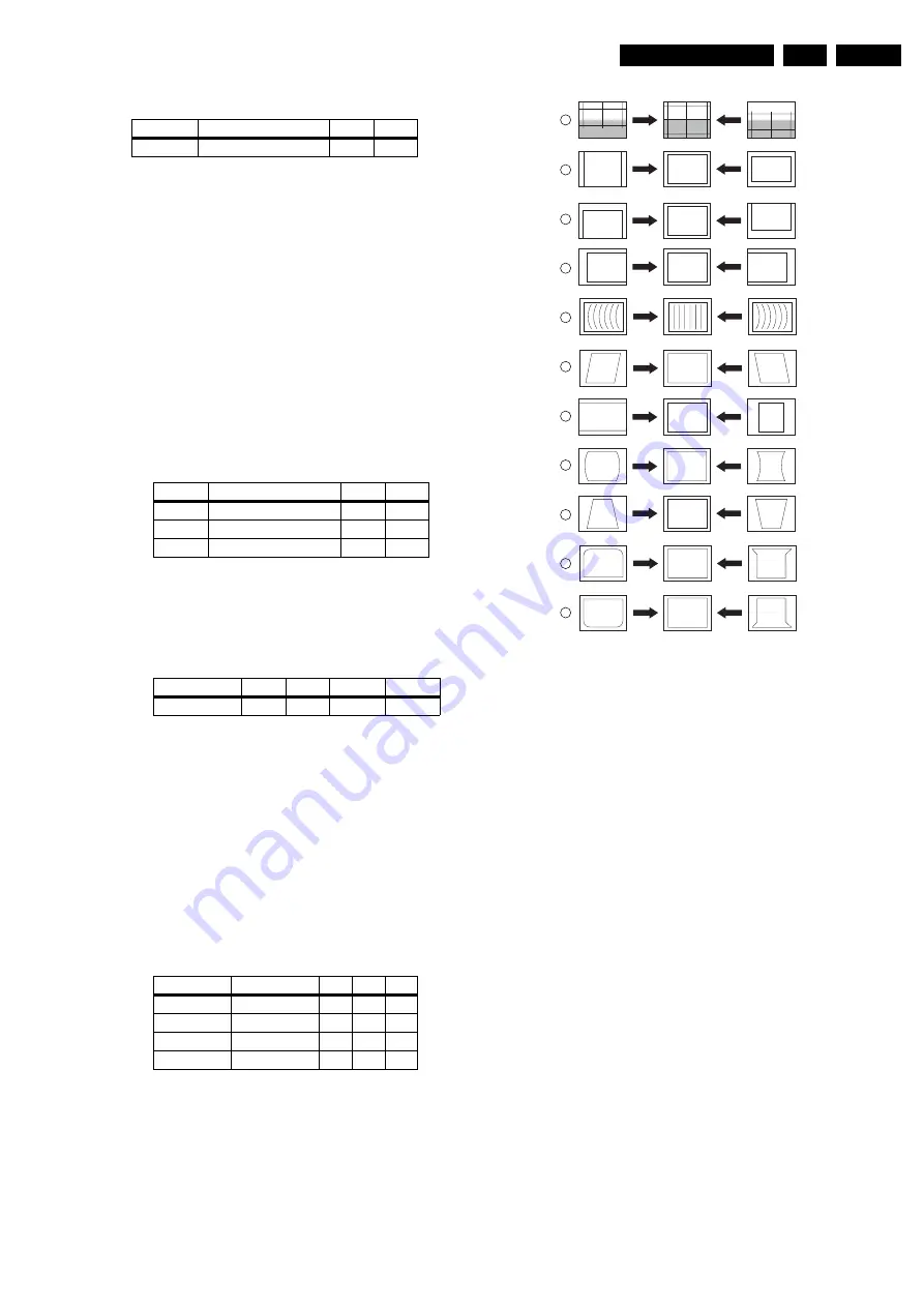
Figure 8-3 Geometry Alignments
1.
Connect an external video pattern generator to the antenna
input of the TV set with a crosshatch test pattern.
2.
Activate the SAM menu as described in the 'Service
Modes, Error Codes and Fault Finding' section.
3.
Go to sub menu GEOMETRY. Now perform the alignments
in the order described below.
Alignments
1.
First set the vertical S-correction (VER.SCOR) value on
'17' for the 30/32", and on '20' for the 34/36" CRTs. Position
the boundary-stripes of the test pattern on the edges of the
picture tube.
2.
Vertical Amplitude (VER. AMPL). Aligns the vertical
amplitude with potentiometer R3603 on the LSP (see Fig.
8-1) so that the complete test pattern is visible.
3.
Vertical shift. Aligns the vertical centering with
potentiometer R3609 on the LSP (see Fig. 8-1) so that the
test pattern is located vertically in the middle. Repeat the
'vertical amplitude' alignment if necessary.
4.
Vertical Slope (VER. SLOPE). Aligns the vertical center of
the picture to the vertical center of the CRT. This is the first
alignment to be performed of the vertical alignments. To
assist in this alignment, set 'SERV.BLK' to 'on' (set
'SERV.BLK' to 'off' after alignment.)
5.
Service Blanking (SERV. BLK). Switches the blanking of
the lower half of the screen on/off (to be used in
combination with the vertical slope alignment).
6.
* East West Width (EW. WIDTH). Aligns the picture width
until the complete test pattern is visible (similar to
Horizontal Amplitude).
7.
* Horizontal Shift (HOR. SHIFT). Aligns the horizontal
center of the picture to the horizontal center of the CRT.
Note:
If the horizontal linearity in wide-screen mode is out
of tolerance, add a “DC-shift correction” panel (3104 328
06230) to connector 1419 of the DAF-panel [diagram I]. On
Tint
Temperature (deg. K)
X
Y
Normal
9300
282
298
Tint
Temperature (deg. K)
X
Y
Warm
6500
315
325
Normal
9300
282
298
Cool
12000
270
280
Screen size
29
30/32
34 LPD
34 MEC
Light output
450cd 380cd
350cd
350cd
Screen size Temperature
R
G
B
29
12000
0
+2
+7
30
12000
0
+3
+7
34
12000
0
+2
+6
36
12000
0
+1
+5
CL 16532043_092.eps
200601
1
2
3
4
5
6
7
8
9
10
11
VERT. SLOPE
VERT. SHIFT
VERT. AMPLITUDE
HOR. SHIFT
EW. WIDTH
EW. PARA
EW. UCORN
EW. LCORN
EW. TRAP
HOR. PARALLEL
HOR. BOW
Summary of Contents for EM1.1A
Page 35: ...Circuit Diagrams and PWB Layouts 35 EM1 1A AA 7 Layout LSP Top Side ...
Page 37: ...Circuit Diagrams and PWB Layouts 37 EM1 1A AA 7 Layout LSP Overview Bottom Side ...
Page 38: ...38 EM1 1A AA 7 Circuit Diagrams and PWB Layouts Layout LSP Part 1 Bottom Side ...
Page 39: ...Circuit Diagrams and PWB Layouts 39 EM1 1A AA 7 Layout LSP Part 2 Bottom Side ...
Page 40: ...40 EM1 1A AA 7 Circuit Diagrams and PWB Layouts Layout LSP Part 3 Bottom Side ...
Page 41: ...Circuit Diagrams and PWB Layouts 41 EM1 1A AA 7 Layout LSP Part 4 Bottom Side ...
Page 116: ...116 EM1 1A AA 7 Circuit Diagrams and PWB Layouts Personal Notes E_06532_013 eps 131004 ...


