background image

SET BLOCK DIAGRAM

3-1

All manuals and user guides at all-guides.com

Summary of Contents for DCM276

Page 1: ...chnical specification 1 2 Service measurement setup 1 3 Service aids 1 4 Instructions on CD playability 2 1 2 2 Block diagram 3 1 Wiring diagram 4 1 Disassembly diagram 5 1 Main board Circuit diagram 6 1 6 5 Layout diagram 6 6 6 7 MCU board Circuit diagram 7 1 Layout diagram 7 2 7 3 Display Key board Circuit diagram 8 1 Layout diagram 8 2 8 3 Power board Circuit diagram 9 1 Layout diagram 9 2 Ipod...

Page 2: ...ral information AC power 230 240 V 50 Hz Operation Power Consumption 25 W Standby Power Consumption 2 W Eco Power Standby Power Consumption 1 W USB Direct Version 2 0 1 1 Dimensions Main Unit W x H x D 542 x 238 x 102 mm Weight Main Unit 3 935 kg TECHNICAL SPECIFICATION 1 2 Type Versions Features Board in used DCM 276 Service policy DISPLAY BOARD MAIN BOARD POWER BOARD KEY BOARD TIPS C Component L...

Page 3: ...1 LF Voltmeter e g PM2534 DUT S N and distortion meter e g Sound Technology ST1700B Frame aerial e g 7122 707 89001 Tuner AM MW LW To avoid atmospheric interference all AM measurements have to be carried out in a Faraday s cage Use a bandpass filter or at least a high pass filter with 250Hz to eliminate hum 50Hz 100Hz RF Generator e g PM5326 Ri 50 Bandpass 250Hz 15kHz e g 7122 707 48001 LF Voltmet...

Page 4: ...re connected with the same potential as the mass of the set via a wrist wrap with resistance Keep components and tools also at this potential ESD CLASS 1 LASER PRODUCT GB Safety regulations require that the set be restored to its original condition and that parts which are identical with those specified be used Safety components are marked by the symbol Lead free All manuals and user guides at all...

Page 5: ...N Y playability ok check playability check playability return set Customer complaint CD related problem fast lens cleaning 1 2 3 For flap loaders access to CD drive possible cleaning method 4 is recommended INSTRUCTIONS ON CD PLAYABILITY 2 1 Exchange CDM 1 4 For description see following pages All manuals and user guides at all guides com ...

Page 6: ... or copy protected CD In case problems remain the customer is requested to contact the workshop directly The lens cleaning method 3 should be mentioned in the addendum sheet The final wording in national language as well as the printing is under responsibility of the Regional Service Organizations 4 LIQUID LENS CLEANING Because the material of the lens is synthetic and coated with a special anti r...

Page 7: ...SET BLOCK DIAGRAM 3 1 All manuals and user guides at all guides com ...

Page 8: ...SET WIRING DIAGRAM 4 1 MCU PCB MCU PCB All manuals and user guides at all guides com ...

Page 9: ...ove 2 screws E as indicated to loosen the Key Board 3 Remove 5 screws F as indicated to loosen the Display Board 4 Remove 2 screws G as indicated to loosen the Power Board 1 Remove 8 screws A as indicated to loosen the speaker cabinet 2 Remove 4 screws B as indicated 3 Remove the rubber foot as indicated 4 Remove 2 screws C as indicated to loosen the Rear cabinet A All manuals and user guides at a...

Page 10: ...6 1 6 1 CIRCUIT DIAGRAM MAIN BOARD PART 1 All manuals and user guides at all guides com ...

Page 11: ...6 2 6 2 CIRCUIT DIAGRAM MAIN BOARD PART 2 All manuals and user guides at all guides com a l l g u i d e s c o m ...

Page 12: ...6 3 6 3 CIRCUIT DIAGRAM MAIN BOARD PART 3 All manuals and user guides at all guides com ...

Page 13: ...6 4 6 4 CIRCUIT DIAGRAM MAIN BOARD PART 4 All manuals and user guides at all guides com ...

Page 14: ...6 5 6 5 CIRCUIT DIAGRAM MAIN BOARD PART5 All manuals and user guides at all guides com ...

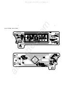
Page 15: ...6 6 6 6 LAYOUT DIAGRAM MAIN BOARD AND SOME SMALL BOARD TOP SIDE All manuals and user guides at all guides com ...

Page 16: ...6 7 6 7 LAYOUT DIAGRAM MAIN BOARD AND SOME SMALL BOARD BOTTOM SIDE All manuals and user guides at all guides com a l l g u i d e s c o m ...

Page 17: ...CIRCUIT DIAGRAM MCU BOARD 7 1 7 1 All manuals and user guides at all guides com ...

Page 18: ...7 2 7 2 LAYOUT DIAGRAM MCU BOARD TOP SIDE All manuals and user guides at all guides com ...

Page 19: ...LAYOUT DIAGRAM MCU BOARD BOTTOM SIDE 7 3 7 3 All manuals and user guides at all guides com ...

Page 20: ...8 1 8 1 CIRCUIT DIAGRAM DISPLAY BOARD AND KEY BOARD All manuals and user guides at all guides com ...

Page 21: ...8 2 8 2 LAYOUT DIAGRAM DISPLAY BOARD All manuals and user guides at all guides com a l l g u i d e s c o m ...

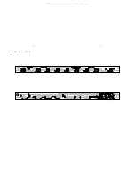
Page 22: ...8 3 8 3 LAYOUT DIAGRAM KEY BOARD All manuals and user guides at all guides com ...

Page 23: ...9 1 9 1 CIRCUIT DIAGRAM POWER BOARD All manuals and user guides at all guides com ...

Page 24: ...9 2 9 2 LAYOUT DIAGRAM POWER BOARD All manuals and user guides at all guides com ...

Page 25: ...10 1 10 1 CIRCUIT DIAGRAM iPod JACK BOARD All manuals and user guides at all guides com ...

Page 26: ...10 2 10 2 LAYOUT DIAGRAM iPod JACK BOARD All manuals and user guides at all guides com a l l g u i d e s c o m ...

Page 27: ...11 1 11 1 CIRCUIT DIAGRAM SW BOARD LAYOUT DIAGRAM SW BOARD All manuals and user guides at all guides com ...

Page 28: ...12 1 12 1 SET EXPLODED VIEW All manuals and user guides at all guides com ...

Page 29: ...10026731 TOP KEYS 227 996510026754 POWER ON KEYS 228 996510026727 EJECT KEYS 229 996510026737 DOOR LENS 230 996510012604 CONNECTOR SLEEVE 230 996510026722 IPOD DOOR LENS 231 996510026736 LED LIGHT GUIDE LENS 232 996510026742 DUCT 233 996510011396 NAIL 234 994000002818 DOOR MOTOR PULLY 235 996510026717 COSMETIC RING J001 994000001939 16P FFC 1MM L60MM J002 996510012093 11P FFC 1mm L 100mm J005 9965...

Page 30: ... DISPLAY SHD1911 TP 1 LED401 996500042438 LED LAMP 2x5x7mm WHITE LED402 996500042438 LED LAMP 2x5x7mm WHITE LED402 996500042438 LED LAMP 2x5x7mm WHITE LED404 996500042438 LED LAMP 2x5x7mm WHITE LED405 996500042438 LED LAMP 2x5x7mm WHITE U401 996510020783 IC ET8862Q KEY BOARD ASSEMBLY LED403 996510026705 LED LAMP 3mm SW401 996500042444 TACT SWITCH 6x6mm 4 3mm SW402 996500042444 TACT SWITCH 6x6mm 4 ...

Page 31: ...IC HT1381 IC601 996510020772 IC SI636165TS IC602 996510022969 IC HWD809R 2 63V IC603 996510021319 IC BX8804 IC605 996510020761 IC XC6206P122PR 1 2V IC607 996510020771 IC SST39VF800A X191 996510024804 CRYSTAL 32 768KHZ 3x8mm X600 996510008326 CRYSTAL 12 MHzHC 49 US H 3 5mm Note Only these parts mentioned in the list are normal service parts 13 2 All manuals and user guides at all guides com a l l g...

Page 32: ...2 AC cord set 55 12NC is changed Added SCREW accessory Version 1 0 314178534200 Version 1 1 314178534201 V Version 1 2 314178534202 P12 2 Change LEFT and RIGHT SPK Front for both 05 and 55 14 1 All manuals and user guides at all guides com ...

Reviews: