EN
8
3
Pr
ess the
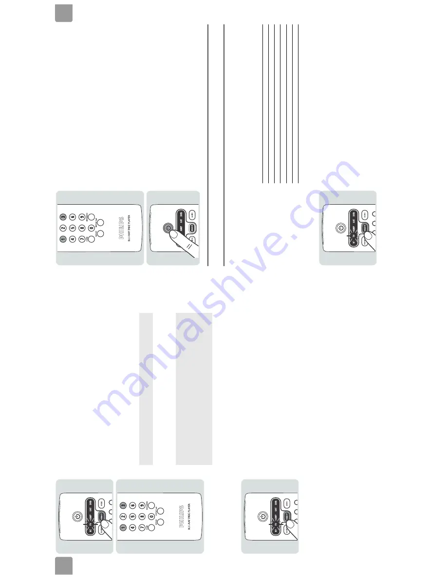
mode selector until the
TV
light comes on.
4
Find th
e
first code f
o
r the TV in the
TV code list (r
ef
er to ’Codes’ on p
age 16
).
5
Pr
ess-and-h
old the
1
and
3
.
6
When the
TV
li
ght flashes tw
o times
, r
e
lease the
1
and
3
.
7
Enter the cod
e fr
om s
tep 4.
8
Mak
e
sur
e that
y
o
u can
oper
ate
the TV w
ith t
h
e
univ
ersal r
e
mote contr
ol.
Re
fe
r t
o
’Ov
er
vie
w’ on page 5 f
o
r an o
ver
vie
w of the functions of the k
e
ys and the buttons.
Sear
ch automaticall
y f
o
r the cor
re
ct code
1
T
u
rn the TV on with
its o
w
n r
e
m
o
te contr
ol or the contr
ols on the TV
.
2
Go
to
the first T
V
chan
nel.
3
Pr
ess the
mode selector until the
TV
light comes on.
Afte
r the first
and second digit
s, the
TV
light fl
ashes one ti
me. Af
ter
the thi
rd di
gi
t,
the
TV
l
ight
goes off and flashes tw
o t
imes.
If the
device does not react
correctly to the uni
ve
rsal
remote
control
:
1
F
ind the next code in
the code list.
2
G
o b
ack to step
5.
OR
:
1
S
e
arch a
u
to
m
ati
ca
lly f
o
r the corre
ct
code
.
EN
9
4
Pr
ess-and-h
old the
1
and
3
.
5
When the
TV
li
ght flashes tw
o times
, r
e
lease the
1
and
3
.
6
Pr
ess the
stand-b
y button.
>
T
he
unive
rs
a
l r
emote
contr
ol searc
hes automatic
ally
fo
r the signa
l tha
t
turns
the TV
off.
Eac
h
time that
the
univer
sal r
emote contr
ol tr
an
smits a sign
al, th
e
TV
light in the display
flashes
.
7
When the
TV i
s turne
d off, pr
e
ss the st
and-b
y k
e
y.
8
Mak
e
sur
e that
y
o
u can
oper
at
e the TV w
ith t
h
e
univ
ersal r
e
mote contr
ol.
Re
fe
r t
o
’Ov
er
vie
w’ on page 5 f
o
r an o
ver
vie
w of the functions of the k
e
ys an
d the buttons.
Enjo
y
V
o
lume buttons
De
pending on t
h
e sel
ect
ed mode
, the v
o
lume but
tons
ar
e assi
gned
to the TV or t
h
e
am
pl
ifier
: These
ar
e the factor
y se
tti
ngs:
/i
Y
o
u can change the assign
ment of
the v
o
lume
contr
ols.
Fo
r
ex
ample
,
yo
u
can
assign
the
vo
lume button in
the
TV
mod
e to the amplifier
:
1
Se
lect t
h
e
TV
mode
.
Mode
Volume bu
ttons
BD
TV
TV
TV
AMP
Amplifier
SA
T
TV
DVD
TV
Summary of Contents for BDP9000
Page 8: ...EN 8 4 BDP9000 Technical Reference 4 1 2 Wiring Diagram Figure 4 1 2 ...
Page 12: ...EN 12 4 BDP9000 Technical Reference 4 5 Video Driver SM5302 block diagram VIC3 Figure 4 5 1 ...
Page 36: ...EN 36 9 BDP9000 Circuit Diagrams and PWB Layouts 9 2 SMPS SMPS PCB Figure 9 2 1 ...
Page 40: ...EN 40 9 BDP9000 Circuit Diagrams and PWB Layouts 9 6 S5L3700 DDR Memory Main PCB Figure 9 6 1 ...
Page 42: ...EN 42 9 BDP9000 Circuit Diagrams and PWB Layouts 9 8 S5L3700 Power GND Main PCB Figure 9 8 1 ...
Page 43: ...Circuit Diagrams and PWB Layouts BDP9000 9 EN 43 9 9 DDR Termination C Main PCB Figure 9 9 1 ...
Page 45: ...Circuit Diagrams and PWB Layouts BDP9000 9 EN 45 9 11 ATA ATAPI Main PCB Figure 9 11 1 ...
Page 46: ...EN 46 9 BDP9000 Circuit Diagrams and PWB Layouts 9 12 S5L3700 Video In Main PCB Figure 9 12 1 ...
Page 50: ...EN 50 9 BDP9000 Circuit Diagrams and PWB Layouts 9 16 DMN8602 DDR Main PCB Figure 9 16 1 ...
Page 55: ...Circuit Diagrams and PWB Layouts BDP9000 9 EN 55 9 21 Power Main PCB Figure 9 21 1 ...
Page 59: ...Circuit Diagrams and PWB Layouts BDP9000 9 EN 59 9 25 Front Front PCB Figure 9 25 1 ...
Page 60: ...EN 60 9 BDP9000 Circuit Diagrams and PWB Layouts 9 26 MEMORY CAED MEMORY PCB Figure 9 26 1 ...
Page 61: ...Circuit Diagrams and PWB Layouts BDP9000 9 EN 61 9 27 POWER SUB PCB Figure 9 27 1 ...
Page 66: ...EN 66 9 BDP9000 Circuit Diagrams and PWB Layouts 9 32 Front PCB component side Figure 9 32 1 ...
Page 67: ...Circuit Diagrams and PWB Layouts BDP9000 9 EN 67 9 33 Front PCB conductor side Figure 9 33 1 ...
Page 68: ...EN 68 9 BDP9000 Circuit Diagrams and PWB Layouts 9 34 Memory Key PCB Figure 9 34 1 ...
Page 69: ...Circuit Diagrams and PWB Layouts BDP9000 9 EN 69 9 35 Front Key PCB Figure 9 35 1 ...
Page 73: ...Directions for Use BDP9000 11 EN 73 11 Directions for Use ...


