background image

User Manual BDL4230E

RETURN TO THE CONTENTS

1.    UNPACKING AND INSTALLATION

1.1.    UNPACKING
• This product is packed in a carton, together with the standard accessories.
• Any other optional accessories will be packed separately.
• The weight of the product differs - depending on the type. Due to the size and weight it is recommended to move it by 

2 people.

• The protective glass and the glass substrate are installed on the front of the product. Since both glass can be broken 

and scraped easily, the product has to be handled with care. Never place the product with the glass faced down unless 
it is protected with pads.

• After opening the carton, ensure that the content is in good condition and complete.

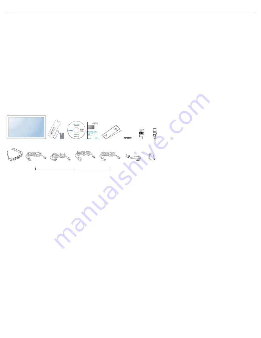
1.2.    PACKAGE CONTENTS
Please verify that you received the following items with your package content:

• Please make sure that for all other regions, apply a power cord that conforms to the AC voltage of the power socket 

and has been approved by and complies with the safety regulations of the particular country.

• You might like to save the package box and packing material for shipping the monitor.
• External speakers and table stands are prepared as options.

1.3.    INSTALLATION NOTES
• Due to the high power consumption, always use the plug exclusively designed for this product. If an extended line is 

required, please consult your service agent.

• The product should be installed on a flat surface to avoid tipping. The distance between the back of the product and the 

wall should be maintained for proper ventilation. Avoid installing the product in the kitchen, bathroom or any other 
places with high humidity so as not to shorten the service life of the electronic components.

• The product can normally operate only under 4000m in height. It might abnormally function at a place over 4000m in 

height and do not install and operate there.

1. LCD monitor
2. Remote control with batteries
3. CD-ROM (EDFU and SICP)
4. Quick Start Guide
5. Logo guider
6. PHILIPS logo
7. BNC-to-RCA adapter (x 2)
8. RCA-to-BNC adapter (x 3)
9. Cable retainer (x 2)
10. Power cords
11. VGA cable
12. Main switch cover

1

2

3

5

6

NAFTA

Europe

UK

China

11

10

7

9

4

8

12

Summary of Contents for BDL4230E

Page 1: ...BDL4230E www philips com welcome EN User manual Cleaning and troubleshooting ...

Page 2: ...onitor To avoid the risk of shock or permanent damage to the set do not expose the monitor to dust rain water or excessive moisture environment If your monitor gets wet wipe it with dry cloth as soon as possible If foreign substance or water gets in your monitor please turn the power off immediately and disconnect the power cord Then remove the foreign substance or water and send it to the mainten...

Page 3: ... the monitor out of direct sunlight and away from stoves or any other heat source Remove any object that could fall into the vents or prevent proper cooling of the monitor s electronics Do not block the ventilation holes on the cabinet Keep the monitor dry To avoid electric shock do not expose it to rain or excessive moisture If turning off the monitor by detaching power cable or DC power cord wai...

Page 4: ... installed and used in accordance with the instructions may cause harmful interference to radio communications However there is no guarantee that interference will not occur in a particular installation If this equipment does cause harmful interference to radio or television reception which can be determined by turning the equipment off and on the user is encouraged to try to correct the interfere...

Page 5: ...andards PN 93 T 42107 and PN 89 E 06251 ELECTRIC MAGNETIC AND ELECTRONMAGNETIC FIELDS EMF 1 MMD manufactures and sells many products targeted at consumers which like any electronic apparatus in general have the ability to emit and receive electromagnetic signals 2 One of MMD s leading Business Principles is to take all necessary health and safety measures for our products to comply with all applic...

Page 6: ...ould not be greater than 5A Note The severed plug must be destroyed to avoid a possible shock hazard should it be inserted into a 13A socket elsewhere How to connect a plug The wires in the mains lead are coloured in accordance with the following code BLUE NEUTRAL N BROWN LIVE L GREEN YELLOW EARTH E 1 The GREEN AND YELLOW wire must be connected to the terminal in the plug which is marked with the ...

Page 7: ...3 2006 ޚ 㾘ᅮⱘ䰤䞣㽕 ҹϟDŽ X 㸼 䆹 ᆇ 䋼㟇ᇥ 䆹䚼ӊⱘᶤϔഛ䋼ᴤ Ёⱘ 䞣䍙ߎ SJ T11363 2006 ޚ 㾘ᅮⱘ䰤䞣㽕 DŽ ֱՓ ᳳ䰤 ℸ 䆚ᣛᳳ䰤 कᑈ ˈ ᄤֵᙃѻકЁ ⱘ ᆇ 䋼 ܗ ℷᐌՓ ⱘᴵӊϟϡӮথ さবˈ ᄤֵᙃѻક Փ 䆹 ᄤֵᙃѻકϡӮᇍ ๗䗴៤Ϲ䞡 ᶧ ᇍ Ҏ䑿ǃ䋶ѻ䗴៤Ϲ䞡ᤳᆇⱘᳳ䰤DŽ 䚼ӊৡ ᆇ 䋼 ܗ 䪙 Pb Hg 䬝 Cd Ӌ䫀 Cr 6 㘨㣃 PBB Ѡ㣃䝮 PBDE O O O O O O 䴶ᵓ X X O O O O 䏃ᵓ㒘ӊ X O O O O O 䰘ӊ 䘹 ˈ 㒓ˈ䖲 㒓 X O O O O O 䘹 X O O O O O ...

Page 8: ...itional information on recycling contact www eia org Consumer Education Initiative WASTE ELECTRICAL AND ELECTRONIE EQUIPMENT WEEE Attention users in European Union private households This marking on the product or on its packaging illustrates that under European Directive 2002 96 EG governing used electrical and electronic appliances this product may not be disposed of with normal household waste ...

Page 9: ...OMPONENT VIDEO INPUT 3 3 2 USING S VIDEO INPUT 3 3 3 USING VIDEO INPUT 3 3 4 USING HDMI INPUT 3 4 CONNECTING A PC 3 4 1 USING VGA INPUT 3 4 2 USING DVI INPUT 3 4 3 USING HDMI INPUT 3 5 EXTERNAL AUDIO CONNECTION 3 5 1 CONNECTING EXTERNAL SPEAKERS 3 5 2 CONNECTING EXTERNAL AUDIO DEVICE 3 6 CONNECTING ANOTHER BDL4230E MONITOR 4 OSD MENU 4 1 NAVIGATING THE OSD MENU 4 1 1 NAVIGATING THE OSD MENU USING ...

Page 10: ...PES OF PIXEL DEFECTS DOT DEFINITION 6 3 BRIGHT DOT DEFECTS 6 4 DARK DOT DEFECTS 6 5 PROXIMITY OF PIXEL DEFECTS 6 6 PIXEL DEFECT TOLERANCES 7 CLEANING AND TROUBLESHOOTING 7 1 CLEANING 7 2 TROUBLESHOOTING 8 TECHNICAL SPECIFICATIONS ...

Page 11: ...he safety regulations of the particular country You might like to save the package box and packing material for shipping the monitor External speakers and table stands are prepared as options 1 3 INSTALLATION NOTES Due to the high power consumption always use the plug exclusively designed for this product If an extended line is required please consult your service agent The product should be insta...

Page 12: ...d by a professional technician Notes Metric 6 10mm screws are needed for wall mounting not included The mounting interface should comply with the UL1678 standard in North America The mounting means should strong enough to bear the weight of the monitor approx 24 5kg without stand Note The remote control sensor should be on the lower side when rotating your monitor How to use the logo guider Allowa...

Page 13: ... from the remote control Detects the ambient lighting condition around the monitor Indicates the operating status of the monitor lights blue when the monitor is turned on lights amber when the monitor is in standby mode blinks blue when remote control signal is received blinks amber when the monitor enters DPMS mode off when the main power of the monitor is turned off 1 ...

Page 14: ...e On Screen Display menu is active use these as the PLUS MINUS menu buttons 5 POWER button Use this button to turn the monitor on or put the monitor to standby 6 Power indicator Indicates the operating status of the monitor lights green when the monitor is turned on lights red when the monitor is in standby mode blinks red when the monitor enters DPMS mode off when the main power of the monitor is...

Page 15: ...vice Using a DVI HDMI cable 7 VGA OUT Outputs the VGA signal from the VGA IN jack 8 VGA IN Connect to the VGA output of a computer 9 RS232C OUT IN RS232C network connection input output for the use of loop through function 10 VIDEO IN COMPONENT Component video input YPbPr for connecting to the component output of an AV device 11 VIDEO IN S VIDEO S Video input for connecting to the S Video output o...

Page 16: ...I D VGA COMPONENT S VIDEO and VIDEO AUDIO SOURCE button To activate the audio source selection menu Press it repeatedly to select the video input source from HDMI AUDIO 1 AUDIO 2 and AUDIO 3 Picture format button To switch screen aspect ratio between FULL NORMAL DYNAMIC CUSTOM REAL and 21 9 PIP Picture In Picture buttons ON OFF button To turn PIP mode ON OFF INPUT button To select the input signal...

Page 17: ...d item when OSD menu is on To move the sub picture down in PIP mode PLUS button To increase the adjustment with OSD menu To move the sub picture right in PIP mode MINUS button To decrease the adjustment with OSD menu To move the sub picture left in PIP mode SET button To activate the setting with OSD menu AUTO ADJUST button Note For the VGA input only To execute the AUTO ADJUST function EXIT butto...

Page 18: ...manganese 2 4 3 OPERATING RANGE OF THE REMOTE CONTROL Point the top of the remote control toward the monitor s remote control sensor when pressing a button Use the remote control within a distance of about 10m 33ft from the monitor s remote control sensor and within a horizontal and vertical angle of 45 degrees Note The remote control may not function properly when the remote control sensor on the...

Page 19: ...R VCD 3 3 1 USING COMPONENT VIDEO INPUT 1 Connect the green colored labeled as Y jack of the device to the green colored Y jack of the monitor 2 Connect the blue colored labeled as Pb jack of the device to the blue colored Pb jack of the monitor 3 Connect the red colored labeled as Pr jack of the device to the red colored Pr jack of the monitor 4 Connect the red R and white L audio jacks of the de...

Page 20: ...white L audio jacks of the device to the AUDIO IN AUDIO2 or AUDIO3 jacks of the monitor 3 3 3 USING VIDEO INPUT 1 Connect the Video connector of the external device to the VIDEO IN input of the monitor Use the supplied BNC to RCA adapter if necessary 2 Connect the red R and white L audio jacks of the device to the AUDIO IN AUDIO2 or AUDIO3 jacks of the monitor DVD VCR VCD DVD VCR VCD ...

Page 21: ...HDMI connector of the external device to the HDMI input of the monitor 3 4 CONNECTING A PC 3 4 1 USING VGA INPUT 1 Connect the 15 pin VGA connector of the PC to the VGA IN connector of the monitor 2 Connect the audio cable to the AUDIO IN AUDIO1 input of the monitor DVD VCR VCD PC ...

Page 22: ... to the DVI D connector of the monitor 2 Connect the audio cable to the AUDIO IN AUDIO1 input of the monitor 3 4 3 USING HDMI INPUT 1 Connect the DVI D connector of the PC to the HDMI connector of the monitor using a DVI HDMI cable 2 Connect the audio cable to the AUDIO IN AUDIO1 input of the monitor PC PC ...

Page 23: ...the external speaker SPEAKERS output of the monitor 2 Turn on the monitor Note Before connecting the speaker wires to the monitor turn off your monitor 3 5 2 CONNECTING EXTERNAL AUDIO DEVICE Connect the red R and white L audio jacks of the external audio device to the AUDIO OUT R L jacks of the monitor External speaker External audio device ...

Page 24: ...ill depend on the resolution of the input signal being used Connect the VGA OUT connector of the monitor to the VGA IN connector of another BDL4230E monitor Connect the RS232C OUT connector of the monitor to the RS232C IN connector of another BDL4230E monitor Connect the VIDEO OUT connector of the monitor to the VIDEO IN connector of another BDL4230E monitor Connect the AC OUT connector of the mon...

Page 25: ...ess the MENU button on the remote control to display the OSD menu 2 Press the UP DOWN button to choose the item you want to adjust 3 Press the PLUS SET button to enter the submenu 4 In the submenu press the UP DOWN button to toggle between items or press PLUS MINUS button to adjust settings If there is a submenu press the SET button to enter the submenu 5 Press the EXIT button on the remote contro...

Page 26: ... item you want to adjust 3 Press the ENTER VIDEO SOURCE button to enter the submenu 4 In the submenu press the button to toggle between items or press button to adjust settings If there is a submenu press the ENTER VIDEO SOURCE button to enter the submenu 5 Press the MENU button on the remote control to return to the previous menu or press the MENU button several times to exit the OSD menu ...

Page 27: ...S MINUS button to adjust NOISE REDUCTION Note For VIDEO S VIDEO COMPONENT and HDMI inputs with interlaced video only Adjust to remove the noise in the image You can select a suitable noise reduction level Use the PLUS MINUS button to make selection TINT Note For VIDEO S VIDEO COMPONENT and HDMI inputs only Adjust to change the color tint of the image Use the PLUS MINUS button to adjust Press the P...

Page 28: ...automatically when ambient lighting condition changes Use the PLUS MINUS button to make selection SMART CONTRAST When turned on this function helps enhance image contrast when displaying dark scenes Use the PLUS MINUS button to make selection VIDEO SOURCE Select a video input source Press the SET PLUS button to open the submenu and then press the UP DOWN button to toggle between PICTURE RESET Rese...

Page 29: ...r press the MINUS button to shrink the width of the image CLOCK PHASE Note For the VGA input only Adjust to improve the focus clarity and stability of the image Use the PLUS MINUS button to adjust ZOOM MODE The pictures you receive may be transmitted in 16 9 format widescreen or 4 3 format conventional screen 16 9 pictures sometimes have a black band at the top and bottom of the screen letterbox f...

Page 30: ... selection Select YES and press the SET button to restore settings to factory preset values Press the EXIT button to cancel and then return to the previous menu REAL This mode displays the image pixel by pixel on screen without scaling the original image size 21 9 The picture is enlarged to 16 9 format This mode is recommended when displaying pictures that have black bands at the top and bottom le...

Page 31: ... the monitor Press the SET PLUS button to open the submenu and then press the UP DOWN button to toggle between SPEAKER Set the monitor to play audio using the built in internal speaker external speakers or external audio devices if connected Use the PLUS MINUS button to toggle between AUDIO RESET Reset all settings in the AUDIO menu Press the SET PLUS button to open the submenu and then press the ...

Page 32: ...pen the submenu and then press the UP DOWN button to make selection Select YES and press the SET button to restore settings to factory preset values Press the EXIT button to cancel and then return to the previous menu Notes The PIP function is only available under certain signal source combinations as shown in the table below PIP function available PIP function unavailable The availability of the ...

Page 33: ...inputs three times in a row Use the PLUS MINUS button to make selection LANGUAGE Select the language for the OSD menu Use the PLUS MINUS button to select a language PANEL SAVING Choose to enable the panel saving functions to reduce the risk of the image persistence Press the SET PLUS button to open the submenu and then press the UP DOWN button to toggle between BRIGHTNESS Select ON and the brightn...

Page 34: ...he EXIT button to cancel and then return to the previous menu FACTORY RESET Reset all settings in the PICTURE SCREEN AUDIO PIP CONFIGURATION 1 CONFIGURATION 2 and ADVANCED OPTION menus Press the SET PLUS button to open the submenu and then press the UP DOWN button to make selection Select YES and press the SET button to restore settings to factory preset values Press the EXIT button to cancel and ...

Page 35: ...d Use the PLUS MINUS button to adjust The information OSD will not appear when OFF is selected If 0 is selected the information OSD will remain on the screen SLEEP TIMER Set the monitor to turn itself off to standby mode within an amount of time you specify OFF 24 hours from current time Use the PLUS MINUS button to adjust Note When the SLEEP TIMER is activated the SCHEDULE settings will be disabl...

Page 36: ...TION Select a display gamma value to best suit the image and optimize image brightness and contrast Use the PLUS MINUS button to toggle between SCAN MODE Note For VIDEO S VIDEO COMPONENT and HDMI video mode inputs only Change the display area of the image Use the PLUS MINUS button to toggle between OVERSCAN Display about 95 of the original size of the image The rest of the areas surrounding the im...

Page 37: ...e this monitor as the primary monitor for remote control operation Only this monitor can be operated by the remote control SECONDARY Designate this monitor as the secondary monitor This monitor can not be operated by the remote control and will only receive the control signal from the primary monitor via the RS232C connection LOCK Lock the remote control function of this monitor To unlock press an...

Page 38: ...ss the PLUS button to open the submenu Press the UP DOWN button to toggle between the YEAR MONTH DAY HOUR MINUTE and DAYLIGHT SAVING TIME settings and then press the PLUS MINUS button to adjust SCHEDULE Note You should set up current date and time in DATE AND TIME before using this function This function allows you to program up to seven different scheduled time intervals for the monitor You can s...

Page 39: ... items overlap scheduled power on time has priority over scheduled power off time If there are two schedule items programmed for the same time then the highest numbered schedule has priority MONITOR ID Set the ID number for controlling the monitor via the RS232C connection Each monitor must have an unique ID number when multiple BDL4230E monitors are connected Use the PLUS MINUS button to select a...

Page 40: ...ic Array 75 Hz 78 75 MHz WXGA 1280 768 60 Hz 79 5 MHz 5 3 Wide XGA WXGA 1280 800 60 Hz 79 5 MHz 16 10 Wide XGA SXGA 1280 960 60 Hz 108 MHz 4 3 Super XGA SXGA 1280 1024 60 Hz 108 MHz 5 4 Super XGA WXGA 1360 768 60 Hz 85 5 MHz 16 9 Wide XGA WXGA 1366 768 60 Hz 85 5 MHz 16 9 Wide XGA UXGA 1600 1200 60 Hz 162 MHz 4 3 Ultra XGA HD1080 1920 1080 60 Hz 148 5 MHz 16 9 HD1080 Standard Resolution Active Res...

Page 41: ... or if the PC is disconnected If so press the INPUT button to enter the video mode Also make sure that the PC is connected When horizontal synchronous signals seem irregular in RGB mode check PC power saving mode or cable connections The display settings table complies to the IBM VESA standards and based on the analog input The DVI support mode is regarded as same to the PC support mode The best t...

Page 42: ...some types or combinations of pixel defects are more noticeable than others Philips sets even higher quality standards for those 6 1 PIXELS AND SUB PIXELS A pixel or picture element is composed of three sub pixels in the primary colors of red green and blue Many pixels together form an image When all sub pixels of a pixel are lit the three colored sub pixels together appear as a single white pixel...

Page 43: ...ots 1 pair of dark dots Minimum distance between dark dots Total no of all defective dots 6 6 PIXEL DEFECT TOLERANCES In order to qualify for repair due to pixel defects during the warranty period a PDP TFT panel in a Philips Plasma LCD display must have pixel or sub pixel defects exceeding the tolerances listed in the following table One lit red green or blue sub pixel Two adjacent lit sub pixels...

Page 44: ...loth or a soft lint free cloth If the surface becomes dirty soak a soft lint free cloth in a mild detergent solution Wring the cloth to remove excess liquid Wipe the surface of the display to remove dirt Then use a dry cloth of the same type to dry Do not scratch or hit the surface of the panel with fingers or hard objects of any kind Do not use volatile substances such as insert sprays solvents a...

Page 45: ...e full size of the screen The zoom mode is not correctly set Use the ZOOM MODE or CUSTOM ZOOM function in the SCREEN menu to fine tune display geometry and time frequency parameter Can hear sound but no picture Improperly connected source signal cable Make sure that both video inputs and sound inputs are correctly connected Can see picture but no sound is heard 1 Improperly connected source signal...

Page 46: ...pe A Digital RGB TMDS Video Audio MAX Video 720p 1080p 1920 x 1080 60 Hz WUXGA Audio 48 KHz 2 Channel L R DVI D Input DVI D jack x 1 Digital RGB TMDS Video RGB Input D Sub Jack x 1 15 pin Analog RGB 0 7V p p 75 H CS V TTL 2 2k SOG 1V p p 75 MAX 720p 1080p 1920 x 1080 60 Hz WUXGA 3 5mm Mini jack x 1 Audio 0 5V rms Normal 2 Channel L R RGB Output D Sub Jack x 1 15 pin Analog RGB 0 7V p p 75 H CS V T...

Page 47: ... Stand 26 4 Kg 24 5 Kg Item Specifications Temperature Operational Storage 0 40 C 20 60 C Humidity Operational Storage 20 80 RH No condensation 5 95 RH No condensation Pressure Operational Storage Shipment 800 1100 hPa Altitude 0 2 000 m 700 1100 hPa Altitude 0 3 000 m Item Specifications Type 1 Way 1 Speaker Input 12 W RMS Impedance 8 Output Sound Pressure 82 dB W M Frequency Response 160 Hz 13 K...

Page 48: ......

Reviews: