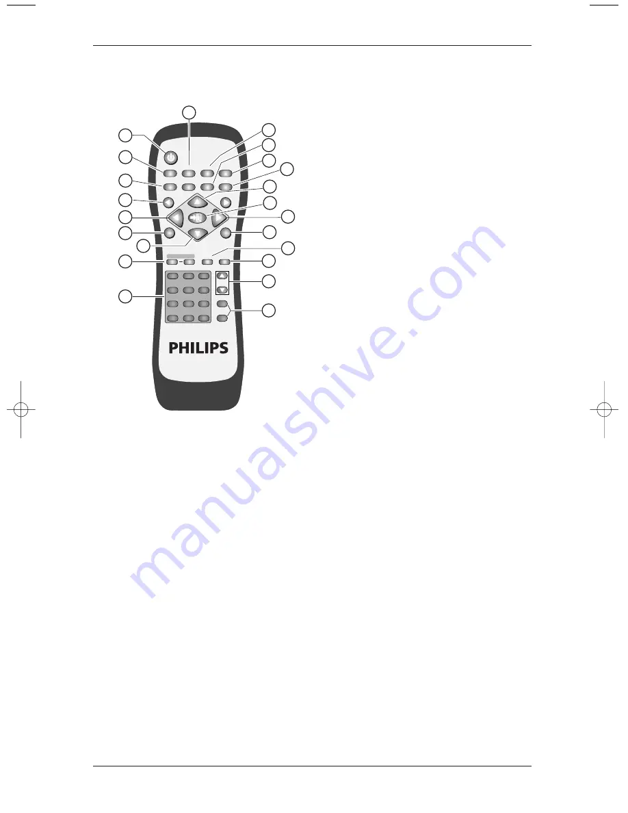
background image

11. AUTO

• The Display automatically adjusts the

phase, vertical/horizontal position when
pressing this button in PC mode.

• The Display chooses the appropriate video

format automatically when pressing this
button in Video mode.

12 DISPLAY

Image and system information display
ON/OFF.

13. Up/Down arrows 

▲ ▼

Use these buttons to adjust the ‘OSD Menu’
up and down or to select ‘Quick Menu’.

14. EXIT

Press this button to exit the ‘OSD Menu’.

15. Left/Right arrows 

p π

Use these buttons to adjust the’OSD Menu’
left and right.

16. INPUT

Press this button to select the signal sources
directly. (Depending on the module, the
available signal source options may be
different).

PC Module

RGB 1

RGB 2 (circular display).

PC  Video Module

RGB1

RGB 2

AV1

S-Video

Y Cb/Pb

Cr/Pr (circular display).

17. PC

Press this button to select the PC signal
source.The signal sources appear in the
following sequence:
RGB 1 (PC Module SUB-D Terminal), RGB 2
(PC Module DVI Terminal).

18. VIDEO

Press this button to select the video input
signal source. The signal sources appear in
the following sequence:
AV1, S-Video,YCb/PbCr/Pr.

19. TV CHANNEL SELECTION

20. VOL +  and  VOL -

Press the volume buttons to increase or
decrease the sound volume level.

Note:

5, 7 and 19 require TV Module installed.

16

User Manual BDS4621

POWER

MENU

INPUT

MTS

PC

WIDE

PIP

FREEZE

AUTO

CH

VOL

VIDEO

EXIT

1

13

17

16

15

14

19

18

20

11

12

7

6

15

5

4

13

2

3

8

9

10

1

2

+

-

3

4

5

6

7

8

9

0

100

ZOOM

RETURN

FULL

WHITE

WOW

MUTE

DISPLAY

MENU

BDS4621_EN.qxd  13-12-2004  10:38  Pagina 16

Summary of Contents for 46-WVGA PLASMA MONITOR BDS4621

Page 1: ...User Manual Benützersanleitung Manuel de l utilisateur Philips Business Solutions G I S F E TYPE NR BDS4621 ...

Page 2: ...Selection of VIDEO Input Mode 22 7 4 Selection of PC Input Mode 22 7 5 OSD Option Adjustment 23 7 6 Sound Adjustment 24 7 7 Zoom Functions 24 7 8 Other Functions 25 7 9 OSD Functions 26 8 OSD Pages and Functions 27 8 1 Display Pages 27 8 2 Image and AV System Page 28 8 3 Audio Page 28 8 4 Language and Screen Saver Page 29 8 5 Misc Page 30 8 6 PIP Settings PC only 31 8 7 User Color Temp AV only 31 ...

Page 3: ...alked on or pinched particularly at plugs convenience receptacles and the point where they exit from the apparatus 11 Only use attachments accessories specified by the manufacturer 12 Use only with a cart stand tripod bracket or table specified by the manufacturer or sold with the apparatus When a cart is used use caution when moving the cart apparatus combination to avoid injury from tip over 13 ...

Page 4: ...be mounted to a wall or ceiling only as recommended by the manufacturer 19 Power Lines An outdoor antenna should be located away from power lines 20 Outdoor Antenna Grounding If an outside antenna is connected to the receiver be sure the antenna system is grounded so as to provide some protection against voltage surges and built up static charges Section 810 of the National Electric Code ANSI NFPA...

Page 5: ...t covering The exclamation point calls attention to features for which you should read the enclosed literature closely to prevent operating and maintenance problems WARNING To reduce the risk of fire or electric shock this appliance should not be exposed to rain or moisture and objects filled with liquids such as vases should not be placed on this apparatus CAUTION To prevent electric shock match ...

Page 6: ...ation holes or slots in the cabinet back Never use thinners insecticide sprays or other chemicals on or near the cabinet as they might cause permanent marring of the cabinet finish END OF LIFE DISPOSAL This Philips product and its packaging contain materials that can be recycled and re used Specialized companies can recycle your product to increase the amount of reusable materials and minimize the...

Page 7: ...s it is protected with pads When opening the carton check that the product is in good condition and that all standard accessories and items are included Whenever possible use the handles on the back of the Display for transport 2 2 Installation Due to the high power consumption always use the plug exclusively designed for this product If an extended line is required please consult your service age...

Page 8: ...s RCA The product supports PC image resolutions up to XGA 1024x768 with a vertical frequency of 85Hz Power Management Function The machine provides an automatic power control function Fan free Design The unit does not require any fans for ventilation eliminating any bothersome noise that may be generated It also lowers the power consumption of the unit Others PIP Function The user may watch video ...

Page 9: ...Power cable will vary depending on shipping area S Video cable 1x SUB D 15 PIN cable 1x AV cable 1x Remote control 1x Including batteries UM 4 2x POWER MENU INPUT MTS PC WIDE PIP FREEZE AUTO CH VOL VIDEO EXIT 1 2 3 4 5 6 7 8 9 0 100 ZOOM RETURN FULL WHITE WOW MUTE DISPLAY MENU ...

Page 10: ...duct then connect the main plug into the wall outlet Note Power plug types vary between countries The power plug shown may not be the type supplied with your set Push the power switch 0 OFF 1 ON The power indicator on the front of the panel should now display red indicating that the Plasma Display is in standby mode 10 User Manual BDS4621 1 2 3 4 ...

Page 11: ...ircular display Note When pressing this button to display OSD Menu the signal sources can be selected by using the arrow buttons MENU Enter OSD Menu and select OSD Menu page the pages appear in the following sequence Display Image for PC input or AV System for Video input Audio Language and Screen Saver Misc Status circular display UP Down buttons A They are used as Up Down buttons in the OSD Menu...

Page 12: ...ction of Enter B These buttons can be used for the adjustment of the volume when the OSD Menu is not shown on the screen Press the left button p to reduce the volume Press the right button π to increase the volume STANDBY ON Is used to activate the Display or return it to standby mode 12 User Manual BDS4621 ...

Page 13: ...roduct to the wall 6 Signal input terminals PC Module PC In Audio For PC Audio input purposes Connects to the PC Phone jack Audio output of the PC RGB Video In For PC display purposes Connects to the SUB D 15 PIN analog output connector of the PC display card DVI Video In For high quality PC display purposes Connects to the DVI I digital output connector of the PC display card RS 232C Is a SUB D 9...

Page 14: ... of the video output device S Video Is a Y C S Video input terminal DIN 4 PIN connecting to the S Video output terminal of the video output device Y CbPb CrPr Is a Component video input terminal RCA connector connecting to the Component output terminal of the video output device Audio 1 Is an audio input terminal connecting to the audio output terminal of the video output device The component vide...

Page 15: ... 8 PIP Use this button to open and adjust the size of the picture in picture in the following sequence Picture in picture open small Screen medium Screen large Picture in picture closed circular display 9 FREEZE Press this button to freeze frame the current screen You may press this button again to continue playing or play shall resume automatically after 100 seconds 10 MUTE Press this button to m...

Page 16: ...options may be different PC Module RGB 1 RGB 2 circular display PC Module Video Module RGB1 RGB 2 AV1 S Video Y Cb Pb Cr Pr circular display 17 PC Press this button to select the PC signal source The signal sources appear in the following sequence RGB 1 PC Module SUB D Terminal RGB 2 PC Module DVI Terminal 18 VIDEO Press this button to select the video input signal source The signal sources appear...

Page 17: ...te control window The effective receiving scope for the signal is 10 meters to the front of the remote control window and 30 degrees to the left or right side and 20 degrees above or below the control window Use of Remote Control To ensure a normal operation the remote control should not be dropped or damaged in any way It should also be kept dry and away from all heat sources Battery replacement ...

Page 18: ...t option RGB 1 DVI connects to digital RGB output interface Input option RGB 2 Note The DVI connector type of the Display is DVI I which does not support analog signal input The RS 232 connector of the Display provides a transmission interface for professional technicians to update firmware without providing additional communication functions 18 User Manual BDS4621 ...

Page 19: ... output device such as DVD or HDTV TUNER The audio should input via Audio 1 INPUT Option Y Cb Pb Cr Pr The S Video terminal connects to the Y C S Video output of a video output device such as S VHS or DVD The audio should input via Audio 2 INPUT Option S Video CVBS In terminal connects to the CVBS Video output of a video output device such asVHS S VHS or DVD The audio should input via Audio 2 INPU...

Page 20: ...at the copper is making good contact with the metal terminal and the colors on the wire match those on the terminal red to red and black to black Close the terminals to clamp the speaker wire in place Note 1 When connecting the external speakers remember to set the speaker to External mode in the Audio page of the OSD Menu Refer to Chapter Basic Operation Note 2 Please use the speaker wire enclose...

Page 21: ...l sources shall appear Use the buttons to select the signal source you want and press the π button to confirm the selection You may also press the INPUT button repeatedly until the signal source you want is highlighted The signal sources are displayed in the following sequence depending on the module the sequence might be different A PC Module B PC Module Video Module POWER MENU INPUT MTS PC WIDE ...

Page 22: ...or enhanced PC modules The signal sources are displayed in the following sequence PC Module Input Menu with modes 22 User Manual BDS4621 POWER MENU INPUT MTS PC WIDE PIP FREEZE AUTO CH VOL VIDEO EXIT 1 2 3 4 5 6 7 8 9 0 100 ZOOM RETURN FULL WHITE WOW MUTE DISPLAY MENU POWER MENU INPUT MTS PC WIDE PIP FREEZE AUTO CH VOL VIDEO EXIT 1 2 3 4 5 6 7 8 9 0 100 ZOOM RETURN FULL WHITE WOW MUTE DISPLAY MENU...

Page 23: ...ect the desired menu page Note The menu pages are displayed in the following sequence circular display Use the buttons to adjust the OSD Menu up and down or to select item from Quick Menu 23 User Manual BDS4621 POWER MENU INPUT MTS PC WIDE PIP FREEZE AUTO CH VOL VIDEO EXIT 1 2 3 4 5 6 7 8 9 0 100 ZOOM RETURN FULL WHITE WOW MUTE DISPLAY MENU Display Image or AV System Audio Language and Screen Save...

Page 24: ...original signal size Note When a video signal is selected you can switch among six screen sizes including Full Fill Aspect Ratio 4 3 to 16 9 LB to 16 9 LB Subtitles to 16 9 and Anamorphic By pressing and holding the ZOOM button you can zoom in on the image gradually By pressing and holding the ZOOM button you can zoom out of the image gradually Note You can only zoom out of the image to its origin...

Page 25: ...e play back system keeps playing when the screen is frozen You can press the PIP button to show the picture in picture screen The screen will change as follows when you press the PIP key consecutively Note The Picture in picture screen can receive video images while the PC outputs the display to the Main Screen so the prerequisites for the display of the sub picture include 1 A video module 2 The ...

Page 26: ... Gamma Colour Space PC User Misc OSD Position OSD Timeout OSD Rotation Colour Temp Reset to default PIP Settings Resolution V Frequency H Frequency PIP Input PIP System Display Brightness Contrast Saturation Hue Sharpness Reset Misc PIP Size PIP Source PIP Position Display Brightness Contrast Saturation Hue Sharpness Reset AV System Aspect Ratio Video Format Audio Volume Treble Bass Balance Mute S...

Page 27: ...er in the Color Temp function of the Misc OSD page Next return to the Display page again VIDEO Display page Screen The Brightness Contrast Saturation Hue Sharpness and Reset can all be adjusted when using Video input signals 27 User Manual BDS4621 Press Menu to Next Page to Select Brightness Contrast Red Green Blue Reset 50 50 50 50 50 Press Menu to Next Page to Select Brightness Contrast Saturati...

Page 28: ...r Anamorphic aspect ratio Video Format Select Auto If you do not know which Video Format to select The display will select the correct signal automatically Other options are NTSC M PAL N PAL M PAL DK 1 SECAM and NTSC J 8 3 Audio Page The adjustable items on the Audio page Volume Treble Bass and Balance Mute can be switched On or Off The Speaker option allows you to switch between Internal or Exter...

Page 29: ...ows you to adjust the length of time between the stages of the Image Move feature Advanced Mode When the Advanced mode is selected press the π button a new page will appear In this page the Gamma value can be selected as well as the Color Space Note The function PC User will only be active if the display is switched in PC Mode Press Menu to Next Page to Select Language English Image reverse Enable...

Page 30: ...C Mode For PIP settings see next page VIDEO Misc page The OSD Position OSD Timeout and OSD rotation options are the same as described above for the PC Misc OSD page Your preferred screen color temperature can be selected from the Color Temp option You can choose from Warm Standard Cool or User By selecting User you can adjust the brightness of Red Green and Blue individually to suit your taste See...

Page 31: ...ed by selecting Off PIP Source Select the desired PIP input source PIP Position Select the desired picture position on the screen Note The Video S Video or Composite terminals must have an input signal for this option 8 7 User Color Temp AV only To access these options select the option User in the Color Temp function in the Misc page You can adjust the brightness of the Red Green and Blue to suit...

Page 32: ... sub picture source and system are also displayed VIDEO Status page The Input source and System are displayed when using video signals 32 User Manual BDS4621 Press Menu to Next Page Signal Information Resolution 1024 x 768 V Frequency 60 Hz H Frequency 48 33 kHz Press Menu to Next Page Signal Information Input Source AV1 System PAL 50 Hz 4 43 MHz ...

Page 33: ...9 OPTIONAL ACCESSORIES Stand BM05111 Attach the Stand to the PDP set Speaker Set 33 User Manual BDS4621 ...

Page 34: ...Ceiling Mount Kit BM01111 34 User Manual BDS4621 ...

Page 35: ...iewing Angle Hor More than 160 degrees Vert More than 160 degrees Sound SRS Surround Power Supply AC 100V 120V 220V 240V 50Hz 60Hz Power Consumption 330W Average Input Terminals PC Module SUB D 15 Pin Analog RGB Input DVI Connector Digital TMDS Input SUB D 9 Pin RS 232 Terminal Video Module S Video Input Mini Din 4 Pin Terminal CVBS Input RCA Terminal Comp Input Y Pb Cb Pr Cr RCA Terminal 2 sets o...

Page 36: ... x 400 640 x 400 640 x 480 640 x 480 640 x 480 640 x 480 640 x 480 800 x 600 800 x 600 800 x 600 800 x 600 800 x 600 832 x 624 1024 x 768 1024 x 768 1024 x 768 1024 x 768 Horizontal Frequency KHz 31 47 37 90 31 50 35 00 37 50 37 86 43 30 35 16 37 90 46 90 48 08 53 70 49 00 48 40 56 50 60 00 68 70 Vertical Frequency Hz 70 08 85 00 60 00 67 00 75 00 72 81 85 00 56 25 60 32 75 00 72 19 85 00 74 00 60...

Page 37: ...ry cloth after cleaning Cleaning of Screen Use a soft cotton cloth to clean the screen gently The screen glass is very fragile When cleaning take care not to scratch or damage the screen surface Don t press or tap the screen to avoid cracking When the screen is dirty use a soft cloth moistened with water to clean the Display Wring water out of the cloth before cleaning to prevent water from penetr...

Page 38: ...n the Remote Control and the Remote Control Window For more information about the Remote Control refer to Chapter Basic Operation Flashing spots or stripes appear on the screen Check that there is no emitter sources Car HV cable or Neon lamp or other possible interference sources Image color or quality deteriorates Check that all the video settings are adjusted appropriately such as brightness con...

Page 39: ...ines from the peripherals are connected properly The power indicator flashes Check that the input signal line is properly connected Check that the screen is not in Power Save mode The input image and signal is not received appropriately Signal Out of Range message appears Select the correct input signal For more information refer to chapter Factory Settings 39 User Manual BDS4621 ...

Page 40: ...stomer controls on the product and installation or repair of antenna systems outside of the product product repair and or part replacement because of misuse accident unauthorized repair or other cause not within the control of Philips Consumer Electronics Europe reception problems caused by signal conditions or cable or antenna systems outside the unit a product that requires modification or adapt...

Page 41: ...readily available MAKE SUREYOU KEEP Please keep your sales receipt or other document showing proof of purchase Attach it to this owner s manual and keep both nearby Also keep the original box and packing material in case you need to return your product BEFORE REQUESTING SERVICE Please check your owner s manual before requesting service Adjustments of the controls discussed there may save you a ser...

Page 42: ...r is an authorized service center he will arrange repair REMEMBER Please record the model and serial numbers found on the product below Also please fill out and mail your warranty registration card promptly It will be easier for us to notify you if necessary MODEL _ _ _ _ _ _ _ _ _ _ _ _ _ _ _ _ _ _ _ SERIAL _ _ _ _ _ _ _ _ _ _ _ _ _ _ _wo_ _ _ 42 User Manual BDS4621 ...

Page 43: ...uct and installation or repair of antenna systems outside of the product product repair and or part replacement because of misuse accident unauthorized repair or other cause not within the control of Philips Consumer Electronics North America reception problems caused by signal conditions or cable or antenna systems outside the unit a product that requires modification or adaptation to enable it t...

Page 44: ...ales receipt or other document showing proof of purchase Attach it to this owner s manual and keep both nearby Also keep the original box and packing material in case you need to return your product BEFORE REQUESTING SERVICE Please check your owner s manual before requesting service Adjustments of the controls discussed there may save you a service call TO GET WARRANTY SERVICE U S A PUERTO RICO OR...

Page 45: ...r any direct indirect special incidental or consequential damages howsoever incurred even if notified of the possibility of such damages REMEMBER Please record the model and serial numbers found on the product below Also please fill out and mail your warranty registration card promptly It will be easier for us to notify you if necessary MODEL _ _ _ _ _ _ _ _ _ _ _ _ _ _ _ _ _ _ _ SERIAL _ _ _ _ _ ...

Page 46: ...46 User Manual BDS4621 ...

Page 47: ...APPENDIX 47 User Manual BDS4621 ...

Page 48: ...ips cannot accept any liability for damages or malfunctioning of the display caused by operation through the serial port The external communication protocol include two parts setup connecting send command Default Serial Port Baud Rate 19200 Parity none Data bits 8 Stop bits 1 Flow Control none 1 1 Setup Connecting A typical Packet transaction session is shown in Figure 1 Figure 1 48 User Manual BD...

Page 49: ...4 0x05 Packet size Low Byte5 0x00 Packet size High Byte6 0xD1 CRC Low Byte7 0xFA CRC High Byte8 0x01 System Info Type Byte9 0x02 Version Packet Payload Byte10 0x00 Number Byte11 0x00 Object ID Byte12 0x00 Leve Table 2 PAK means that PC will follow the received Packet data c Packet same as 1st Packet Table 1 d Same as Ack Table 2 e Packet toTarget Philips PDP structure Table 3 Byte0 0xBE Magic Byte...

Page 50: ...ize CRC 0xBE 0xEF type size_lo size_hi crc_lo crc_hi Table 5 The Packet Header size is fixed at seven bytes Intel byte ordering is used The following code fragments are taken from these source files The Packet Header definition is shown below typedef struct BYTE ePacketType type of the payload WORD nPacketSize size of the payload WORD nCRCPacket CRC for the entire packet PACKET_HEADER Magic Number...

Page 51: ...ng Packet Checksum CRC Each packet is CRC ed using the tables later in this document This number is the CRC value for the complete packet including the Packet Header and Packet Payload The CRC is calculated with the nCRCPacket value initialized to zero 1 1 3 Packet Payload Definition Event Packet Type The Event packet is used by the host system to send virtual events such as Zoom Source Auto Adjus...

Page 52: ... op_BRIGHTNESS has a Target of either MAIN or PIP window 9 12 Operation Value Value of the Set on a set or the Value of the Get on a Return 13 16 Operation Value The Minimum Value of the set of minimum for operation command 17 20 Operation Value The Maximum Value of the set of maximum for operation command 21 24 Operation Value The Increment Value of the set of Increment for operation command Tabl...

Page 53: ...e2 0x02 Packet Type Packet Header Byte3 0x06 Packet size Low Byte4 0x00 Packet size High Byte5 0x80 CRC Low Byte6 0xC7 CRC High Byte7 0xC9 Virtual Byte8 0x00 Event ID Packet Payload Byte9 0x00 Byte10 0x00 Parameter Byte11 0x00 Byte12 0x00 Table 9 b Target return to Host PC Ack like as below Table 10 Ack Byte0 0x06 ACK Table 10 53 User Manual BDS4621 ...

Page 54: ...ctor and Philips Plasma too The wiring between the computer and Philips plasma is a straight through cable A 9 pin female to 9 pin female stright through cable is a very standard part and readily available in many lengths Female D sub9 pinout numbering and definitions on both terminal Pin number Name 2 Transmit 3 Receive 5 Ground PW Serial uses the following default serial port settings Baud Rate ...

Page 55: ...1 4 Software Flow Chart 55 User Manual BDS4621 ...

Page 56: ... 00 00 00 FF 00 00 00 00 00 00 00 00 00 00 00 00 00 00 00 Red 0 BE EF 03 19 00 AA C2 01 DF 02 00 00 00 00 00 00 00 00 00 00 00 00 00 00 00 00 00 00 00 00 00 00 Red 255 BE EF 03 19 00 1A C3 01 DF 02 00 00 00 00 00 00 FF 00 00 00 00 00 00 00 00 00 00 00 00 00 00 00 Green 0 BE EF 03 19 00 01 BA 01 E1 02 00 00 00 00 00 00 00 00 00 00 00 00 00 00 00 00 00 00 00 00 00 00 Green 255 BE EF 03 19 00 B1 BB 0...

Page 57: ...0 3C FF 01 B8 02 00 00 00 00 00 00 00 00 00 00 00 00 00 00 00 00 00 00 00 00 00 00 ColorSpace EBU BE EF 03 19 00 5D 7E 01 B8 02 00 00 00 00 00 00 02 00 00 00 00 00 00 00 00 00 00 00 00 00 00 00 Language BE EF 03 19 00 D3 28 01 0B 02 00 00 00 00 00 00 00 00 00 00 00 English 00 00 00 00 00 00 00 00 00 00 00 Language BE EF 03 19 00 43 E9 01 0B 02 00 00 00 00 00 00 01 00 00 00 00 French 00 00 00 00 00...

Page 58: ...0 00 00 00 00 07 00 00 00 00 00 00 00 00 00 00 00 00 00 00 00 Lower Right BE EF 03 19 00 01 0C 01 22 02 00 00 00 00 00 00 08 00 00 00 00 00 00 00 00 00 00 00 00 00 00 00 OSD Timeout sec 5 5 BE EF 03 19 00 00 25 01 10 02 00 00 00 00 00 00 05 00 00 00 00 00 00 00 00 00 00 00 00 00 00 00 10 10 BE EF 03 19 00 F4 60 01 10 02 00 00 00 00 00 00 0A 00 00 00 00 00 00 00 00 00 00 00 00 00 00 00 255 255 BE E...

Page 59: ...59 User Manual BDS4621 ...

Page 60: ...60 User Manual BDS4621 ...

Reviews: