background image

25

5.2.7.  Advanced option menu

 

 

 

 

 

  

 





  

 

   



















 

Input resolution

Set the resolution of the VGA input. This is only required when the 

display is unable to detect the VGA input resolution correctly.
NOTE:   This item is functional for 

VGA

 input only.

The options are: 
•  {

1024x768

 / 

1280x768

 / 

1360x768 / 1366x768

}

•  {

1400x1050

 / 

1680x1050

}

•  {

1600x1200

 / 

1920x1200

}

•  {

Auto

}: Determines the resolution automatically.

The selected settings will become effective after turning off the power 

and turning it on again.

IR control

Select the operation mode of the remote control when multiple 

displays are connected via an RS232C connection.
•  {

Normal

}


- All displays can be operated normally by the remote 

control unit.

•  {

Primary

} - Designate this display as the primary display for 

remote control operation. Only this display can be operated by the 

remote control.  (In primary mode, IR key will always be processed 

regardless the monitor id/group settings).

•  {

Secondary

} - Designate this display as the secondary display. This 

display can not be operated by the remote control, and will only 

receive the control signal from the primary display via the RS232C 

connection.

•  {

Lock All

} / {

Lock all but Volume

} / {

Lock all but Power

} / 

{Lock 

all except PWR & VOL}-

 Lock the remote control function of this 

display. To unlock, press and hold the [

INFO

 button on the 

remote control for 6 (six) seconds.

Keyboard control

Choose to enable or disable the display keyboard (control buttons) 

function.
•  {

Unlock

} - Enable the keyboard function.

•  {

Lock All

} / {

Lock all but Volume

} / {

Lock all but Power

} / {

Lock all 

except PWR & VOL

-

 Disable the keyboard function.

NOTE:   “Keyboard Control Lock Mode” This function completely 

disables the access to all Keyboard Control functions. To 

enable or disable the keyboard control lock, press both [ ] 

and 

[ ]

 buttons and hold down continuously for more than 3 

seconds.

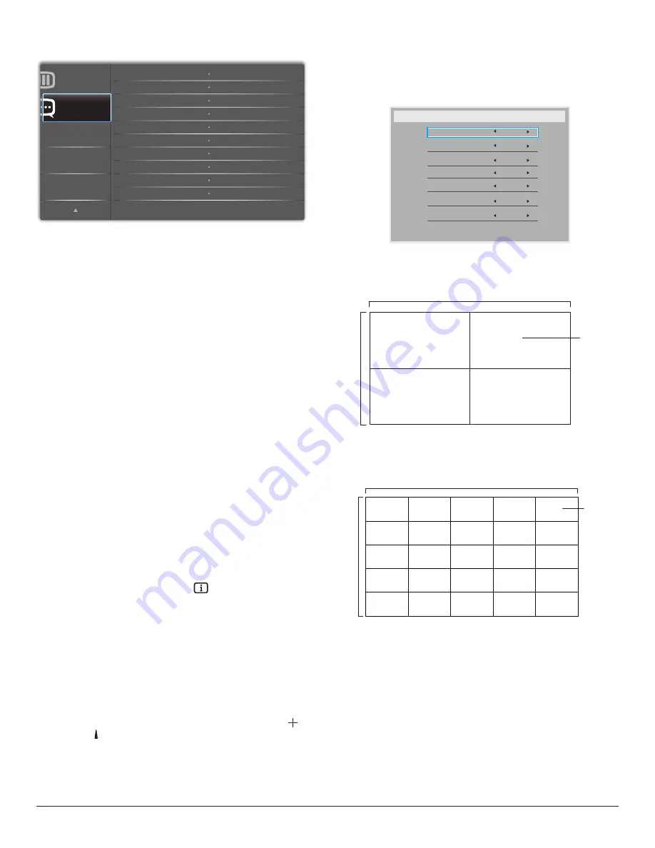
Tiling

With this function you can create a single large-screen matrix (video 

wall) that consists of up to 225 sets of this display (

up to 15-sets on the 

vertical and 15-sets on the horizontal sides

). This function requires a 

daisy-chain connection.



 

 



 



  











Example: 2 x 2 screen matrix (4 displays)

H monitors = 2 displays 

V monitors = 2 displays

1

2

3

4

H monitors

V monitors

Position

Example: 5 x 5 screen matrix (25 displays)

H monitors = 5 displays 

V monitors = 5 displays

1

2

6

7

3

4

8

9

5

10

11

12

13

14

15

16

17

18

19

20

21

22

23

24

25

H monitors

V monitors

Position

•  {

H monitors

} - Select the number of displays on the horizontal side.

•  {

V monitors

} - Select the number of displays on the vertical side.

•  {

Position

} - Select the position of this display in the screen matrix.

•  {

Frame comp.

} - Choose to turn the frame compensation 

function on or off. If selected {

Yes

}, the display will adjust the image 

to compensate for the width of the display bezels in order to 

accurately display the image.

Summary of Contents for 43BDL4031D

Page 1: ...www philips com welcome 32BDL4031D 43BDL4031D 49BDL4031D 55BDL4031D V1 00 User Manual English ...

Page 2: ...as alcohol or ammonia based liquids to clean your display To avoid the risk of shock or permanent damage to the set do not expose the display to dust rain water or an excessively moist environment If your display becomes wet wipe it with dry cloth as soon as possible If a foreign substance or water gets in your display turn the power off immediately and disconnect the power cord Then remove the fo...

Page 3: ... or permanent damage to the set do not expose the display to rain or excessive moisture When positioning the display make sure the power plug and outlet are easily accessible IMPORTANT Always activate a screen saver program during your application If a still image in high contrast remains on the screen for an extended period of time it may leave an after image or ghost image on the front of the sc...

Page 4: ... result in fire or shock hazard do not expose this appliance to rain or excessive moisture This device complies with Part 15 of the FCC Rules Operation is subject to the following two conditions 1 This device may not cause harmful interference and 2 this device must accept any interference received including interference that may cause undesired operation Envision Peripherals Inc 490 N McCarthy Bl...

Page 5: ... BSI approved type 3 Refit the fuse cover If the fitted plug is not suitable for your socket outlets it should be cut off and an appropriate 3 pin plug fitted in its place If the mains plug contains a fuse this should have a value of 5A If a plug without a fuse is used the fuse at the distribution board should not be greater than 5A NOTE The severed plug must be destroyed to avoid a possible shock...

Page 6: ...办法 以下部分列出了本产品中可能包含的有害 物质的名称和含量 部件名称 有害物质 铅 Pb 汞 Hg 镉 Cd 六价铬 Cr VI 多溴联苯 PBB 多溴二苯醚 PBDE 外壳 液晶显示屏 电路板组件 电源适配器 电源线 连接线 遥控器 X 本表格依据SJ T 11364 的规定编制 电路板组件包括印刷电路板及其构成的零部件 如电阻 电容 集成电路 连接器等 O 表示该有害物质在该部件所有均质材料中的含量均在 GB T 26572规定的限量要求以下 X 表示该有害物质至少在该部件的某一均质材料中的含量超出GB T 26572规定的限量要求 上表中打 的部件 应功能需要 部分有害物质含量超出GB T 26572规定的限量要求 但符合欧盟RoHS 法规要求 属于豁免部分 备注 上表仅做为范例 实际标示时应依照各产品的实际部件及所含有害物质进行标示 10 環保使用期限 此標識指期限 十年 電子電...

Page 7: ... 喇叭 選配 風扇 選配 備考1 係指該項限用物質之百分比含量未超出百分比含量基準值 備考2 係指該項限用物質為排除項目 警語 使用過度恐傷害視力 注意事項 1 使用30分鐘請休息10分鐘 2 未滿2歲幼兒不看螢幕 2歲以上每天看螢幕不要超過1小時 警告使用者 此為甲類資訊技術設備 於居住環境中使用時 可能會造成射頻擾動 在此種情況下 使用者會被 要求採取某些適當的對策 Turkey RoHS Türkiye Cumhuriyeti EEEYönetmeliğine Uygundur Ukraine RoHS Обладнання відповідає вимогам Технічного регламенту щодо обмеження використання деяких небезпечних речовин в електричному та електронному обла...

Page 8: ... promotes energy efficiency This product qualifies for ENERGY STAR in the factory default settings and this is the setting in which power savings will be achieved Changing the factory default picture settings or enabling other features will increase power consumption that could exceed the limits necessary to qualify for ENERGY STAR rating For more information on the ENERGY STAR program refer to en...

Page 9: ...disposal of the used battery According to EU directive 2006 66 EC the battery can t be disposed improperly The battery shall be separated to collect by local service Após o uso as pilhas deverão ser entregues ao estabelecimento comercial ou e ou baterias rede de assistência técnica autorizada Information for EAC Month and year of manufacturing please refer information in Rating label Name and loca...

Page 10: ... 15 3 2 Connecting a PC 15 3 3 Connecting Audio Equipment 16 3 4 Connecting Multiple Displays in a Daisy chain Configuration 16 3 5 IR connection 17 3 6 IR Pass through Connection 18 4 Operation 19 4 1 Watch the ConnectedVideo Source 19 4 2 Change Picture Format 19 5 OSD Menu 19 5 1 Navigating the OSD Menu 19 5 2 OSD Menu Overview 19 6 Input Mode 29 7 Pixel Defect Policy 31 7 1 Pixels and Sub Pixe...

Page 11: ...ortation Always keep the carton in a vertical position Do NOT place the carton in any other direction Do NOT place any object on the carton Do NOT apply shock vibration to the product Move the carton by stacker Do NOT drop the product Strong impacts may damage the components inside ...

Page 12: ... 2 x 1 Edge Alignment Kit 1 x 2 Thumb Screw x 8 Items may differ in different locations Display design and accessories may differ from the images shown NOTES For all other regions apply a power cord that conforms to the AC voltage of the power socket and has been approved by and complies with the safety regulations of the particular country Type H05W F 2G or 3G 0 75 or 1 mm2 should be used Keep th...

Page 13: ... Please refer to the following drawing to identify the position of screws 32BDL4031D Fasten the longest screw M6x41 0mm into Hole 1 and Hole 7 of tube to secure it to the display Step 3 Set up the stand using thumb screws Table stand Longer portions should face the front M6xL41 screws Thumb screws To remove the table stands 1 Power off the display 2 Spread a protective sheet on a flat surface 3 Pl...

Page 14: ... M6x41 0mm into Hole 3 and Hole 13 of tube to secure it to the display 49BDL4031D Fasten the longest screw M6x41 0mm into Hole 4 and Hole 14 of tube to secure it to the display 43BDL4031D Fasten the longest screw M6x41 0mm into Hole 5 and Hole 15 of tube to secure it to the display Step 3 Set up the stand using thumb screws Table stand Longer portions should face the front M6xL41 screws Thumb scre...

Page 15: ...mount table stand etc 3 Follow the instructions that came with the base mounting kit Failure to follow the correct mounting procedures could result in damage to the equipment or injury to the user or installer The product warranty does not cover the damage caused by improper installation 4 For the wall mounting kit use the M6 mounting screws with a length 10 mm longer than the thickness of the mou...

Page 16: ...th the bracket To prevent the display from falling in case of earthquake or other natural disaster please consult the manufacturer of the bracket for the mounting location As this product is high and heavy the installation of this product is recommended to be performed by four technicians Ventilation Requirements for enclosure locating Leave a space of 100 mm at the top rear right and left of the ...

Page 17: ... to remove the logo 1 Prepare a piece of paper with a cutting area of logo as a protector to prevent the front bezel from scratching 2 Use a knife and carefully remove the logo sticker with the paper placing beneath 3 Tear off the logo sticker 1 2 3 NOTE We recommend you contact a professional technician when installing the display on a wall We are not responsible for any damage to the product if ...

Page 18: ...o adjacent displays Install the Edge Alignment Kit 1 with 2 PCS of M4 screw Use Edge Alignment Kit 2 for four adjacent displays NOTE When installing the edge alignment kit please consult a professional technician for proper installation We accept no liability for installations not performed by a professional technician ...

Page 19: ...to adjust the selected item while OSD menu is on 8 MENU button Return to previous menu while OSD menu is on or to activate the OSD menu when OSD menu is off 9 Remote control sensor and power status indicator Receives command signals from the remote control Indicates the operating status of the display without OPS Lights green when the display is turned on Lights red when the display is in standby ...

Page 20: ...tion NOTES This display s remote control sensor will stop working if the jack IR IN is connected To remotely control your A V device via this display refer to page 18 for IR Pass Through connection 7 AUDIO IN Audio input forVGA source 3 5mm stereo phone 8 USB PORT B Reserve forTouch model 9 HDMI1 IN 10 HDMI2 IN HDMI video audio input 11 DVI IN DVI I video input 12 DVI OUT DVI orVGA video output 13...

Page 21: ...ES This display s remote control sensor will stop working if the jack IR IN is connected To remotely control your A V device via this display refer to page 18 for IR Pass Through connection 7 AUDIO IN Audio input forVGA source 3 5mm stereo phone 8 USB PORT B Reserve forTouch model 9 HDMI1 IN 10 HDMI2 IN HDMI video audio input 11 DVI IN DVI I video input 12 DVI OUT DVI orVGA video output 13 AUDIO O...

Page 22: ...control Do not allow any liquid to get inside the remote control If water has entered the remote control wipe the remote control with a dry cloth immediately Do not place the remote control near heat and steam sources Do not attempt to disassemble the remote control unless you need to place batteries in the remote control 2 2 3 Operating range of the remote control Point the top front of the remot...

Page 23: ...ntrolled Group ID number Main Menu Go to the previous level of menu Source Menu Exit from the source menu Volume Menu Decrease the volume Main Menu Go to the next level of menu or set selected option Source Menu Go to the selected source Volume Menu Increase the volume 7 button Root Menu Go to the OSD of IR daisy chain in Primary Secondary mode Main Menu Confirm an entry or selection 8 ADJUST butt...

Page 24: ... 0 and 1 for display No 1 press 1 and 1 for display No 11 The numbers available are 01 255 2 If no button is pressed within 10 seconds it will exit from the ID mode 3 If a wrong button is pressed wait for 1 second until the red LED lights off and then turns on again then press the correct digits 4 Press ENTER button to confirm your selection The red LED blinks twice and then lights off NOTE Press ...

Page 25: ... 3 1 1 Using HDMI video input DVD VCR VCD HDMI Out HDMI IN HDMI1 IN HDMI2 IN 3 2 Connecting a PC 3 2 1 Using DVI input PC IR OUT AUDIO LINE IN USB B HDMI 1 IN HDMI 2 IN VGA AUDIO IN Audio Out DVI Out DVI IN DVI IN DVI OUT 3 2 2 Using HDMI input HDMI Out HDMI IN HDMI1 IN HDMI2 IN PC ...

Page 26: ...onnecting Multiple Displays in a Daisy chain Configuration You can interconnect multiple displays to create a daisy chain configuration for applications such as a menu board 3 4 1 Display control connection Connect the RS232 OUT connector of DISPLAY 1 to the RS232 IN connector of DISPLAY 2 DISPLAY 1 PC DISPLAY 2 RS 232C IN RS 232C RS 232C OUT RS 232C IN PC RJ 45 RS 232C OUT RS 232C IN DISPLAY 1 DI...

Page 27: ... connector of DISPLAY 2 PC DISPLAY 1 DISPLAY 2 DVI IN DVI DVI OUT DVI IN 3 5 IR connection IR IN External IR Receiver IR IN IR OUT DISPLAY 1 DISPLAY 2 RS 232C OUT RS 232C IN DISPLAY 1 DISPLAY 2 NOTE 1 The remote control sensor of this display will stop working if the IR IN is connected 2 IR loop through connection can support up to 9 displays 3 IR in daisy chain via RS232 connection can support up...

Page 28: ...18 3 6 IR Pass through Connection DVD VCR VCD DVD VCR VCD Remote Control IR OUT IR IN ...

Page 29: ...reen press to display the menu of Audio source 5 1 2 Navigating the OSD menu using the display s control buttons 1 Press MENU button to display the OSD menu 2 Press or button to choose the item you want to adjust 3 Press button to enter the submenu 4 In the submenu press or button to toggle among items press or button to adjust settings If there is a submenu press button to enter the submenu 5 Pre...

Page 30: ...g changes when smart power setting has changed Overscan Change the display area of the image ON Set to display area about 95 OFF Set to display area about 100 Picture reset Reset all settings in the Picture menu Select Yes and press SET button to restore to factory preset data Press EXIT button to cancel and then return to the previous menu 5 2 2 Screen menu P Audio PIP Screen Picture Configuratio...

Page 31: ...dio menu P Audio PIP Screen Picture Configuration 1 Treble Bass Maximum volume Minimum volume Balance Volume Audio out line out Mute 50 50 50 30 Off Off 30 0 100 Audio source Sync Volume Analog P Audio PIP Screen Picture Configuration 1 Audio reset Action Balance Adjust to emphasize left or right audio output balance Treble Adjust to increase or decrease higher pitched sounds Bass Adjust to increa...

Page 32: ...ct audio from the main picture Sub Select audio from the sub picture PIP reset Reset all settings in the PIP menu to factory preset values The PIP function is available only for certain signal source combinations as shown in the table below HDMI1 HDMI2 DVI DisplayPort VGA Custom HDMI1 O X X O O X HDMI2 X O X O O X DVI X X O O O X DisplayPort O O O O O O VGA O O O O O O Custom X X X O O O O PIP fun...

Page 33: ...power indication LED on or off Choose On for normal use Network settings DHCP Enable Cannot modify IP address Subnet mask Default gateway DHCP Disable Can manualy input IP address Subnet mask Default gateway Configuration1 reset Reset all settings in Configuration1 menu to the factory preset values Factory reset Reset all settings in the OSD menus of Picture Screen Audio PIP Configuration1 Configu...

Page 34: ...Version XXXXXXXX XXXXX XXXXX XXXXX DP version DisplayPort support mode The options are DP 1 1 Default DP 1 1 single stream clone mode DP 1 2 SST DP 1 2 Single stream clone mode DP 1 2 MST DP 1 2 Multi Stream NOTE 1 The DP version must be set the same for all daisy chain displays 2 For 3840x2160 the dot clock timing should be 533MHz 3 DP 1 1 not support 4K 60Hz timing Window selection Select the wi...

Page 35: ...n the remote control for 6 six seconds Keyboard control Choose to enable or disable the display keyboard control buttons function Unlock Enable the keyboard function Lock All Lock all butVolume Lock all but Power Lock all except PWR VOL Disable the keyboard function NOTE Keyboard Control Lock Mode This function completely disables the access to all Keyboard Control functions To enable or disable t...

Page 36: ...ol for the customer which doesn t know how to adjust the clock for daylight saving on and off It does not adjust the real time clock automatically Problem is that there are no stable rules per region or country when to adjust the clock To solve this the user must be able to set the daylight saving start en stop date When daylight saving correction is on user selectable then the real time clock sho...

Page 37: ...akes priority over scheduled power off time If there are two schedule items programmed for the same time the highest numbered schedule takes priority For example if schedule items 1 and 2 both set the display to power on at 7 00 AM and off at 5 00 PM then only schedule item 2 will take effect HDMI with One Wire CEC control Off Disable CEC Default On Enable CEC Auto signal detection Choose to let t...

Page 38: ... in the Advanced option menu to factory preset values 1 Press OK or button to enter the submenu 2 Press or button to select Reset and press the OK button to restore settings to factory preset values 3 Press the button or select Cancel and press the OK button to cancel and then return to the previous menu ...

Page 39: ... 60 000 22 1280x720 52 5 70 000 23 CVT 2 3MA 1280 x768 47 776 59 870 24 CVT 2 3MA 1280 x768 60 289 74 893 25 CVT 1280x800 49 7 59 810 26 CVT 1280x800 62 8 74 930 27 VESA 1280x960 60 60 000 28 VESA 1280x1024 63 981 60 020 29 SUN WS 1280x1024 71 691 67 189 30 VESA 1280x1024 79 976 75 025 31 VESA Standard AddDMT 1360x768 47 712 60 015 32 VESA Standard AddDMT 1366x768 47 712 59 790 33 VESA reduced bla...

Page 40: ...cy select mode exists select 60Hz vertical and 31 5KHz horizontal In some cases abnormal signals such as stripes might appear on the screen when the PC power is turned off or if the PC is disconnected If so press the INPUT button to enter the video mode Also make sure that the PC is connected When horizontal synchronous signals seem irregular in RGB mode check PC power saving mode or cable connect...

Page 41: ... picture element is composed of three sub pixels in the primary colors of red green and blue Many pixels together form an image When all sub pixels of a pixel are lit the three colored sub pixels together appear as a single white pixel When all are dark the three colored sub pixels together appear as a single black pixel Other combinations of lit and dark sub pixels appear as single pixels of othe...

Page 42: ...iquid crystal display LCD panels This is known within the industry as Mura which is a Japanese term for unevenness It is used to describe an irregular pattern or area in which uneven screen uniformity appears under certain conditions Mura is a result of the deterioration of the liquid crystal alignment layer and is most commonly caused by long term operation under high ambient temperatures It is a...

Page 43: ...ree cloth If the surface becomes dirty soak a soft lint free cloth in a mild detergent solution Wring the cloth to remove excess liquid Wipe the surface of the display to remove dirt Then use a dry cloth of the same type to dry Do not scratch or hit the surface of the panel with fingers or hard objects of any kind Do not use volatile substances such as insert sprays solvents and thinners Cabinet C...

Page 44: ... incorrectly to underscan 3 If the image exceeds the screen size Scan Mode may need to be set to Underscan Use the Zoom mode or Custom zoom function in the Screen menu to fine tune display geometry and time frequency parameter Can hear sound but no picture Source signal cable is connected improperly Make sure that both video inputs and sound inputs are correctly connected Can see picture but no so...

Page 45: ...will show again if it disappear 3 Default setting ID NO 0 GP NO 0 this setting can control all displays by IR The can change ID NO to control signal display by Monitor ID The UP DOWN can change GP NO to control multi display by Group ID The first display is always controlled by IR How is the RC working Daisy chain no connection of RS232 and IR cable No setting is required Connect with IR cables an...

Page 46: ...nternal Speakers 10W L 10W R RMS 8Ω 82 dB W M 160 Hz 13 KHz Audio Output 3 5mm phone jack x 1 0 5V rms Normal 2 Channel L R Audio Input 3 5mm phone jack x 1 0 5V rms Normal 2 Channel L R RS232 2 5mm Phone jack x 2 RS232 in RS232 out RJ 45 RJ 45 Jack x 1 8 pin 100 baseT HDMI Input HDMI Jack x 2 Type A 19 pin Digital RGB TMDS Video Audio MAX Video 720p 1080p 3840 x 2160 30 Hz Audio 48 KHz 2 Channel ...

Page 47: ...2 1 Kg Gross Weight 8 50 Kg 14 7 Kg 20 0 Kg 25 4 Kg Energy Efficiency Class B A A A Visible Screen Size 800 1 mm 31 5 inches 1080 mm 42 5 inches 1232 mm 48 5 inches 1387 mm 54 6 inches On Mode Power Consumption W 55 W 59 W 69 W 85 W Annual Energy Consumption kWh 81 kWh 86 kWh 101 kWh 124 kWh Standby Power Consumption W 0 50 W 0 50 W 0 50 W 0 50 W Off Mode Power Consumption W 0 W 0 W 0 W 0 W Displa...

Page 48: ...s N V All rights reserved Philips and the Philips Shield Emblem are registered trademarks of Koninklijke Philips N V and are used under license from Koninklijke Philips N V Specifications are subject to change without notice ...

Reviews: