Service Modes, Error Codes, and Fault Finding
5.
5.
Service Modes, Error Codes, and Fault Finding
Index of this chapter:
5.1 Test Points
5.2 Service Modes
5.3 Problems and Solving Tips (related to CSM)
5.4 ComPair
5.5 Error Codes
5.6 The Blinking LED Procedure
5.7 Protections
5.8 Repair tips
5.9 Software Downloading
5.1
Test Points
The chassis is equipped with test points printed on the circuit
board assemblies.
Perform measurements under the following conditions:
•
Service Default Mode.
•
Video: colour bar signal.
•
Audio: 3 kHz left, 1 kHz right.
5.2
Service Modes
Service Default Mode (SDM) and Service Alignment Mode
(SAM) offer several features for the service technician, while
the Customer Service Mode (CSM) is used for communication
between a Philips Customer Care Centre (P3C) and a
customer.
There is also the option of using ComPair, a hardware interface
between a computer (see requirements below) and the TV
chassis. It offers the ability of structured troubleshooting, test
pattern generation, error code reading, software version read-
out, and software upgrading.
Minimum requirements:
a Pentium processor, Windows 95/
98, and a CD-ROM drive (see also paragraph “ComPair”).
Remark:
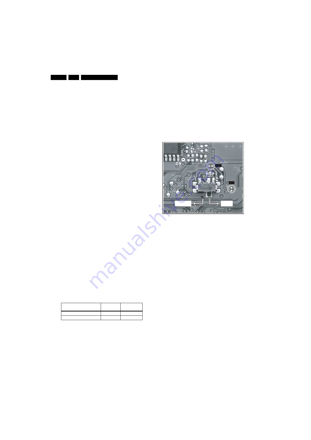
The silk screen printing is not correct for the SAM/
SDM indication. For the correct location of these pins, see
figure ”Service pads”.
5.2.1
Service Default Mode (SDM)
Purpose
•
To create a pre-defined setting, to get the same
measurement results as given in this manual.
•
To override SW protections.
•
To start the blinking LED procedure.
Specifications
Table 5-1 SDM default settings
•
All picture settings at 50% (brightness, colour, contrast).
•
All sound settings at 50%, except volume at 25%.
•
All service-unfriendly modes (if present) are disabled, like:
–
(Sleep) timer.
–
Child/parental lock.
–
Blue mute.
–
Automatic volume limiter (AVL).
–
Auto switch-off (when no video signal was received for
10 minutes).
–
Skip/blank of non-favourite pre-sets.
–
Smart modes.
–
Auto store of personal presets.
–
Auto user menu time-out.
How to activate SDM
Use one of the following methods:
•
Use the standard RC-transmitter and key in the code
“062596”
, directly followed by the “MENU” button.
Note:
It is possible that, together with the SDM, the main
menu will appear. To switch it off, push the “MENU” button
again.
Figure 5-1 Service pads
•
Short for a moment the two solder pads on the SSB, with
the indication “SDM” (see figure ”Service pads”). Activation
can be performed in all modes, except when the TV has a
problem with the main microprocessor.
Caution
: If the SDM is activated via the pins, all the
software-controlled protections are de-activated.
•
Use the DST-emulation feature of ComPair.
•
Use the “DEFAULT” button on the Dealer Service Tool
(RC7150).
How to navigate
When you press the “MENU” button on the RC transmitter, the
TV will toggle between the SDM and the normal user menu
(with the SDM mode still active in the background).
How to exit SDM
Use one of the following methods:
•
Switch the TV to STANDBY via the RC-transmitter.
•
Press the “EXIT” button on the DST.
•
Via a standard customer RC-transmitter: key in “00”-
sequence.
5.2.2
Service Alignment Mode (SAM)
Purpose
•
To perform (software) alignments.
•
To change option settings.
•
To easily identify the used software version.
•
To view operation hours.
•
To display (or clear) the error code buffer.
Specifications
•
Operation hours counter.
•
Software version.
Region
Freq. (MHz)
Default
system
Europe, AP-PAL/Multi
475.25
PAL B/G
NAFTA, AP-NTSC, LATAM
61.25 (ch. 3)
NTSC M
E_14620_151.eps
290704
SDM
SAM
NORMAL
TV MODE
SW UPGRADE
MODE


