


© MMD 2010
Page 13 of 45
76
221TE2L LCD
General Product Specification
3.2.2.4
Table of page (TOP)
A type of teletext transmission in which special pages are transmitted that give information about
other pages in the transmission.
3.2.2.5
Link control byte (LCB)
It is contained in a packet 27 to validate the links for the color keys.
3.2.2.6
Video programming system (VPS)
A mechanism by which the broadcast ID is transmitted using Teletext transmission.
3.3 EXTERNAL
INTERFACE
3.3.1 VIDEO SIGNAL REQUIREMENTS
x
CVBS input -
1000mVpp (including 300 mV sync level), terminated with input
impedance of 75
:
.
x
S-Video input -
Y: 1000mVpp, C: 300mVpp, terminated with input impedance of
75
:
.
x
Component video input -
Y: 1000mVpp, PbPr: ±350mVpp, terminated with input
impedance of 75
:
. 480i/p, 576i/p, 720p, 1080i
ʿ
1080
̃ʳ
signal
handling capability.
x
HD ready -
HD ready logo required.
Display
engine:
¾
The minimum native resolution of the display (e.g.
LCD, PDP) or display engine (e.g. DLP) is 720
physical lines in wide aspect ratio.
Video
Interfaces:
¾
The display device accepts HD input via:
Analog YPbPr. “HD ready” displays support
analog YPbPr as a HD input format to allow full
compatibility with today's HD video sources in
the market. Support of the YPbPr signal should
be through common industry standard
connectors directly on the HD ready display or
through an adaptor easily accessible to the
consumer; and:
¾
DVI or HDMI HD capable inputs accept the
following HD video formats:
1280x720 @ 50 and 60Hz progressive scan
(“720p”)
1920x1080 @ 50 and 60Hz interlaced (“1080i”)
¾
The DVI or HDMI input supports copy protection
(HDCP).
Summary of Contents for 221TE2LB/00
Page 5: ...221TE2L LCD 5 Installation Front View Product Description Rear View ʳ ...
Page 6: ...6 221TE2L LCD Installation ...
Page 7: ...221TE2L LCD 7 Installation ...
Page 8: ...8 221TE2L LCD Installation ...
Page 9: ...221TE2L LCD 9 Installation ...
Page 10: ...10 221TE2L LCD Installation ...
Page 11: ...221TE2L LCD 11 Troubleshootingʳ ...
Page 12: ...12 221TE2L LCD Troubleshooting ...
Page 14: ...14 221TE2L LCD On Screen Display Supported display resolutionsʳ ʳ ...
Page 21: ...221TE2L LCD 21 Mechanical Instruction 18 Disassemble the hingeÆ 1 screw Screw driver ...
Page 23: ...221TE2L LCD 23 FAQs Frequently Asked Questions ...
Page 24: ...24 221TE2L LCD FAQs Frequently Asked Questions ...
Page 27: ...221TE2L LCD 27 Service tool Hardware PCM code 12NC 5E L8215 001 996510019769 ...
Page 43: ...221TE2L LCD 43 LULQJ LDJUDP ...
Page 44: ...44 221TE2L LCD ORFN LDJUDP ...
Page 53: ...S calar Diagram C B A 221TE2L LCD 53 ...
Page 56: ...Power Diagram C B A 56 221TE2L LCD ...
Page 57: ...Power Diagram C B A 221TE2L LCD 57 ...
Page 59: ...LED Diagram C B A 221TE2L LCD 59 ...
Page 61: ...Control Diagram C B A 221TE2L LCD 61 ...
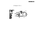
Page 63: ...IR Diagram C B A 221TE2L LCD 63 ...
Page 109: ...Exp lode d Vie w 221TE2L LCD 109 ...
Page 114: ...ʳ 114 221TE2L LCD Repair Flow Chart No Display ...


