


© MMD 2010
Page 8 of 45
221TE2L LCD
71
General Product Specification
3.1 POWER
3.1.1 POWER SUPPLY FEATURES
x
AC line voltage range -
90Vac ~ 264Vac.
x
AC line frequency range -
50/60 Hz
r
3 Hz.
x
DC tact switch -
Minimal power consumption when switch off.
x
Inrush current -
< 40A at 240Vac when cold start.
x
Leakage current -
< 0.5mA at 240Vac.
x
Power factor correction -
According to EN61000-3-2
3.1.2 POWER CONSUMPTION & MEASURE THE FOLLOWING VOLTAGE
x
Normal on(2 lamp) – On mode (MAX): w/audio 1Khz,Volume=100 , 40Watt
On mode (Typ.) w/o audio , 32Watt
x
Normal on (4lamp)-
On mode (MAX): w/audio 1Khz,Volume=100 , 55Watt
On mode (Typ.) w/o audio , 45Watt
x
Power Saving (VGA only)-- < 0.5W, RC standby mode + RED LED
x
Standby (DC off, Press RC Power Key)- < 0.5W, RC standby mode + RED LED
x
Power off (Press Key BD Power key)- < 0.5W, RC standby mode + LED Off
ˣ̂̊˸̅ʳ˶̂́̆̈̀̃̇˼̂́ʳ
˴́˷ʳ˘˿˸˶̇̅˼˶˴˿ʳ̇˸̆̇ʳ˹̂̅ʳˣ
3.1.3 POWER
MODE
Power Off mode
:
The mains plug is not connected or, the power supply is switched off. The
system has no power available.
Standby mode
:
The TV signal processing hardware is switched off. The micro-controller
is operating and waiting for a command
TV mode
:
The LCD display is switched on. The TV set is tuned to a channel or
external source. The micro-controller is processing all incoming signals
and commands and also controls the TV hardware.
PC mode
:
The system is displaying PC video input.
Power Saving mode:
The system is the same as Standby mode as there is no PC video when
system is in PC mode.
Wake Up keys:
Key: CH+, CH-, Power
RC:
CH+, CH-, Power
Summary of Contents for 221TE2LB/00
Page 5: ...221TE2L LCD 5 Installation Front View Product Description Rear View ʳ ...
Page 6: ...6 221TE2L LCD Installation ...
Page 7: ...221TE2L LCD 7 Installation ...
Page 8: ...8 221TE2L LCD Installation ...
Page 9: ...221TE2L LCD 9 Installation ...
Page 10: ...10 221TE2L LCD Installation ...
Page 11: ...221TE2L LCD 11 Troubleshootingʳ ...
Page 12: ...12 221TE2L LCD Troubleshooting ...
Page 14: ...14 221TE2L LCD On Screen Display Supported display resolutionsʳ ʳ ...
Page 21: ...221TE2L LCD 21 Mechanical Instruction 18 Disassemble the hingeÆ 1 screw Screw driver ...
Page 23: ...221TE2L LCD 23 FAQs Frequently Asked Questions ...
Page 24: ...24 221TE2L LCD FAQs Frequently Asked Questions ...
Page 27: ...221TE2L LCD 27 Service tool Hardware PCM code 12NC 5E L8215 001 996510019769 ...
Page 43: ...221TE2L LCD 43 LULQJ LDJUDP ...
Page 44: ...44 221TE2L LCD ORFN LDJUDP ...
Page 53: ...S calar Diagram C B A 221TE2L LCD 53 ...
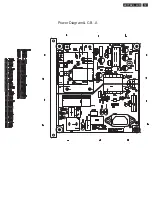
Page 56: ...Power Diagram C B A 56 221TE2L LCD ...
Page 57: ...Power Diagram C B A 221TE2L LCD 57 ...
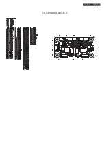
Page 59: ...LED Diagram C B A 221TE2L LCD 59 ...
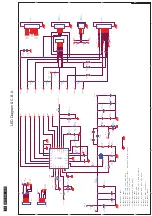
Page 61: ...Control Diagram C B A 221TE2L LCD 61 ...
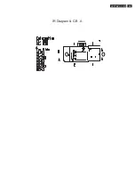
Page 63: ...IR Diagram C B A 221TE2L LCD 63 ...
Page 109: ...Exp lode d Vie w 221TE2L LCD 109 ...
Page 114: ...ʳ 114 221TE2L LCD Repair Flow Chart No Display ...


