


18
200WB7 LCD
DDC Instructions
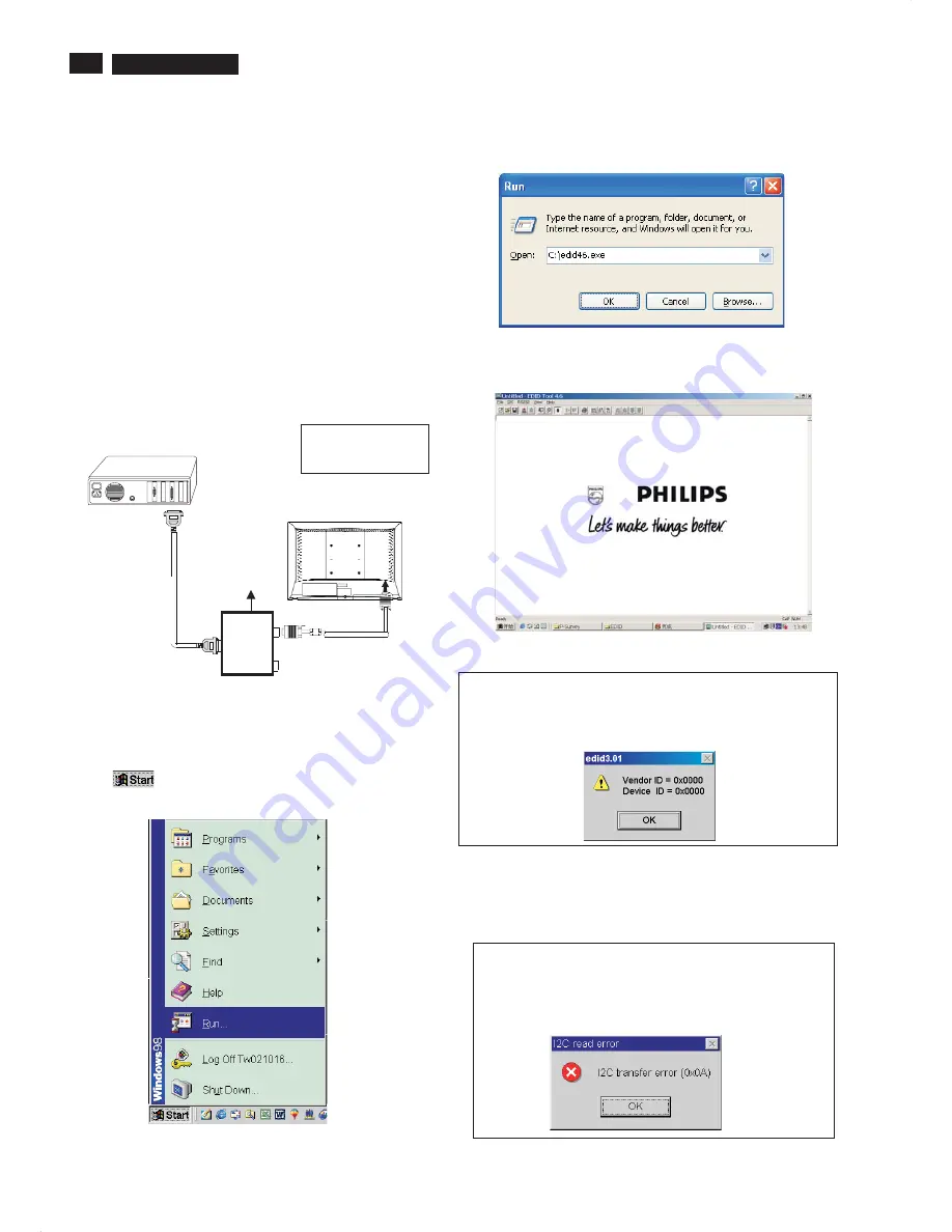
Step 3: Installation of EDID46.EXE
Method 1: Start on DDC program
Start Microsoft Windows.
1. The Program"EDID46.EXE" in service manual cd-rom be copyed to C:\ .
2. Click
, choose Run at start menu of Windows as shown
In Fig. 5.
Fig. 5
4. Click OK button. The main menu appears (as shown in Fig. 7).
This is for initialize alignment box.
Fig. 7
Fig. 6
3. At the submenu, type the letter of your computer's hard disk drive
followed by :EDID46 (for example, C:\EDID46, as shown in Fig. 6).
Note 2: During the loading, EDID46 will verify the EDID data which just
loaded from monitor before proceed any further function, once
the data structure of EDID can not be recognized, the following
error message will appear on the screen as below. Please
confirm following steps to avoid this message.
1. The data structure of EDID was incorrect.
2. DDC IC that you are trying to load data is empty.
3. Wrong communication channel has set at configuration setup
windows.
4. Cables loosed or poor contact of connection.
1
Fig. 8
Note 1: If the connection is improper, you will see the following error
message (as shown in Fig. 8) before entering the main menu.
Meanwhile, the (read EDID) function will be disable. At this
time, please make sure all cables are connected correctly and
fixedly, and the procedure has
been performed properly.
Fig. 9
Configuration and procedure
There is no Hardware DDC (DDC IC) anymore. Main EEPROM stores
all factory settings and DDC data (EDID code) which is also called
Software DDC. The following section describes the connection and
procedure for Software DDC application. The main EEPROM can be re-
programmed by enabling '' factory memory data write'' function on the
DDC program (EDID46.EXE).
Initialize alignment box
In order to avoid that monitor entering power saving mode due
to sync will cut off by alignment box, it is necessary to initialize
alignment box before running programming software
(EDID46.EXE). Following steps show you the procedures and
connection.
Step 1: Supply 8-12V DC power source to the Alignment box by
plugging a DC power cord .
Step 2: Connecting printer cable and D-Sub cable of monitor as Fig. 4
Fig. 4
PC
1
=
Power connector
2
=
D-S
U
B connector
T
o
printer
port
(L
TP1)
DC Power
8-12 V
Printer
Port
To
Monitor
To PC
1
2
-----
>
-----
>
Summary of Contents for 200WB7EB/27
Page 7: ...7 200WB7 LCD Only available for Asia Pacific Model Main Menu Sub Menu On Screen Display ...
Page 29: ...29 200WB7 LCD Wiring Diagram ...
Page 31: ...31 200WB7 LCD Scaler Diagram 1 ...
Page 32: ...32 200WB7 LCD Scaler Diagram 2 ...
Page 33: ...33 200WB7 LCD Scaler Diagram 3 ...
Page 34: ...34 200WB7 LCD Scaler Diagram 4 ...
Page 35: ...35 200WB7 LCD Scaler Diagram 5 ...
Page 36: ...36 200WB7 LCD Scaler Board C B A 1 ...
Page 37: ...37 200WB7 LCD Scaler Board C B A 2 ...
Page 38: ...38 200WB7 LCD Scaler Board C B A 3 ...
Page 39: ...39 200WB7 LCD Control Diagram ...
Page 40: ...40 200WB7 LCD Control Board C B A ...
Page 41: ...41 200WB7 LCD USB Diagram ...
Page 42: ...42 200WB7 LCD USB Board C B A ...
Page 43: ...43 200WB7 LCD Power Diagram 1 ...
Page 44: ...44 200WB7 LCD Power Diagram 2 ...
Page 45: ...45 200WB7 LCD Power Board C B A 1 ...


