
SLEEP
EJECT
SYSTEM MENU
REPEAT
AUDIO
REPEAT A-B SUBTITLE
SMART SOUND
SMART PICTURE
TV/DVD
MENU
DVD
MENU
VOL
CH
MUTE
1
2
3
4
5
6
7
8
9
0
CC
A/CH
OK
PAUSE
STOP
PLAY
MODE
POWER
TV
VCR
OSD
L/Mono
Monitor out
VIDEO
S-VIDEO
AV1 in
Y
Pb
Pr
AV2 in
AUDIO
R
COMPONENT VIDEO INPUT
S-VIDEO
OUT
OUT
OUT
L
R
AUDIO
VIDEO
COMP VIDEO
Y
Pb
Pr
CVI
2
1
3
5
4
H
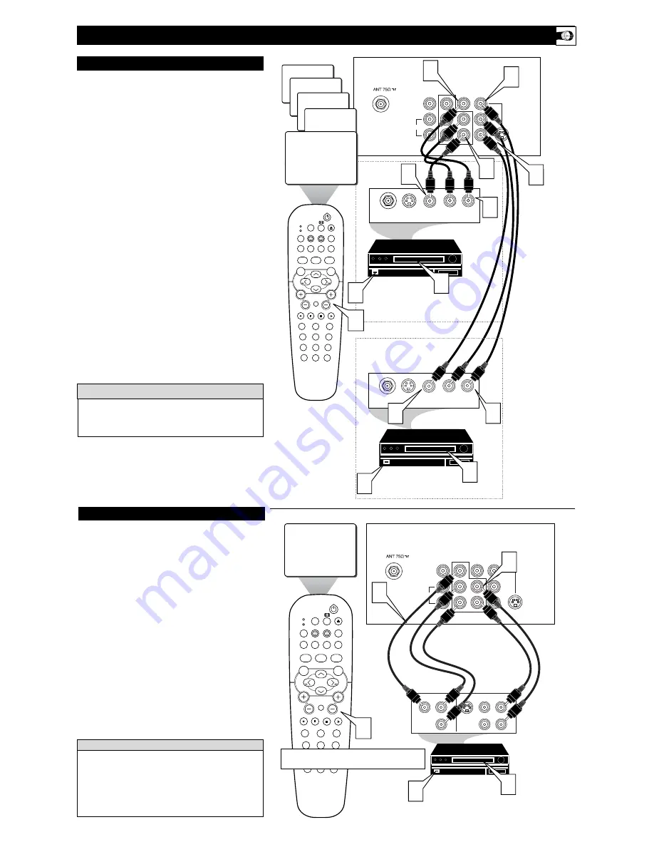
OOKING UP THE
TV
C
omponent Video inputs provide for the highest possible color
and picture resolution in the playback of digital signal source
material, such as with DVD players. The color difference signals
(Pb, Pr) and the luminance (Y) signal are connected and received
separately, which allows for improved color bandwidth informa-
tion (not possible when using composite video or S-Video connec-
tions).
1
Connect the Component (Y, Pb, Pr) Video OUT
jacks
from the DVD player (or similar device) to the (Y, Pb, Pr)
in(put) jacks on the TV. When using the Component Video
Inputs, it is best not to connect a signal to the AV1 in Video
Jack.
2
Connect the red and white AUDIO CABLES
to the
Audio (left and right) output jacks on the rear of the acces-
sory device to the Audio (L and R) AV1 in Input Jacks on
the TV.
3
Turn the TV and the DVD (or digital accessory device)
ON.
4
Press the CH +, – buttons
to scroll the available channels
until CVI appears in the upper left corner of the TV screen.
5
Insert a DVD disc into the DVD player and
press the
PLAY
button on the DVD Player.
C
OMPONENT
V
IDEO
I
NPUTS
The description for the component video connectors may differ
depending on the DVD player or accessory digital source equip-
ment used (for example, Y, Pb, Pr; Y, B-Y, R-Y; Y, Cr, Cb).
Although abbreviations and terms may vary, the letters
b
and
r
stand for the blue and red color component signal connectors,
and
Y
indicates the luminance signal. Refer to your DVD or
digital accessory owner’s manual for definitions and connection
details.
H
ELPFUL
H
INT
3
T
he TV’s audio/video input jacks are for direct picture and
sound connections between the TV and a VCR (or similar
device) that has audio/video output jacks. Both the AV1 and AV2
Input Jack connections are shown on this page, but either one can
be connected alone. Follow the easy steps below to connect your
accessory device to the AV1 and AV2 in Jacks located on the back of
the TV.
1
Connect the VIDEO (yellow) cable
to the VIDEO
AV1 in
(or AV2 in) jack on the back of the TV.
2
Connect the AUDIO (red and white) cables
to the
AUDIO (left and right)
AV1 in
(or AV2 in) jacks on the
rear of the TV.
3
Connect the VIDEO (yellow) cable
to the VIDEO OUT
jack on the back of the VCR (either one or two) or acces-
sory device being used.
4
Connect the AUDIO (red and white) cables
to the
AUDIO (left and right) OUT jacks on the rear of the VCR
(either one or two) or accessory device being used.
5
Turn the VCR (either one or two) or accessory device
and the TV ON.
6
Press the CH + or – buttons
on the remote control to
select the AV1 channel for accessory device number one, or
the AV2 channel for accessory device number two. AV1 or
AV2 will appear in the upper left corner on the TV screen
depending on the channel chosen.
7
With either of the VCRs (or accessory devices) ON and a
prerecorded tape (CD, DVD, etc.) inserted,
press the
PLAY button
to view the tape on the television.
AV1 & AV2 I
NPUTS
SLEEP
EJECT
SYSTEM MENU
REPEAT
AUDIO
REPEAT A-B SUBTITLE
SMART SOUND
SMART PICTURE
TV/DVD
MENU
DVD
MENU
VOL
CH
MUTE
1
2
3
4
5
6
7
8
9
0
CC
A/CH
OK
PAUSE
STOP
PLAY
MODE
POWER
TV
VCR
OSD
L/Mono
Monitor out
VIDEO
S-VIDEO
AV1 in
Y
Pb
Pr
AV2 in
AUDIO
R
COMPONENT VIDEO INPUT
24
SVHS
CVI
AV1
AUDIO OUT
R L
S-VIDEO
OUT
ANT/CABLE
OUT
VIDEO
OUT
3
AUDIO OUT
R L
S-VIDEO
OUT
ANT/CABLE
OUT
VIDEO
OUT
3
4
5
7
1
AV2
2
4
2
1
5
7
6
Note:
The Audio/Video cables needed for this connection are
not supplied with your TV. Please contact your dealer or Philips
at 800-531-0039 for information about purchasing the needed
cables.
c
c
C
HECK
I
T
O
UT
AUDIO IN
(RED/WHITE)
VCR TWO (or accessory device)
(EQUIPPED WITH VIDEO AND
AUDIO OUTPUT JACKS)
VIDEO IN
(YELLOW)
BACK OF VCR
BACK
OF TV
AV1
Connection
AV2
Connection
VCR ONE (or accessory device)
(EQUIPPED WITH VIDEO AND
AUDIO OUTPUT JACKS)
AUDIO CABLES
(RED/WHITE)
COMPONENT
VIDEO CABLES
(Green, Blue, Red)
BACK OF TV
ACCESSORY DEVICE
EQUIPPED WITH COMPONENT
VIDEO OUTPUTS.
The CVI connection will be dominate over the AV1 in Video Input.
When a Component Video Device is connected as described, it is best
not to have a video signal connected to the AV1 in Video Input jack.


