26
Go to cover page
DDC Instructions (Continued)
150X3M LCD
Re-programming Digital DDC IC
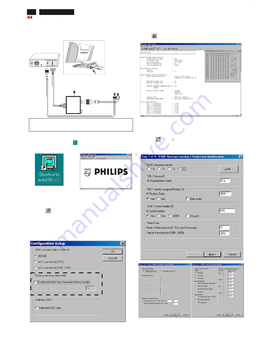
Connecting all cables and alignment box as shown in
Fig. 9.
Step 1:
After connection for Digital DDC application, if it is still in Analog DDC
application of EDID301.
Exit EDID301 program before Digital DDC application.
Fig. 10
Fig. 11
Step 2: Initialize alignment box
(Shortcut of EDID301.EXE on
Double click EDID301 icon (as shown in Fig. 10) which is
on the screen of Windows Wallpaper.
Bring up main menu of EDID301 as shown in Fig. 11.
Windows Wallpaper already.)
Step 3: Read DDC data from monitor
1.
Click icon from the tool bar to bring up the Channels
Configuration Setup windows as shown in Fig. 11.
2.
Select the DDC2B as the communication channel.
Disable "Factory memory data write" for Digital DDC
application
as shown in Fig. 12.
3.
Click OK button to confirm your selection.
4. Click icon (Read EDID function) to read DDC EDID data from
monitor. The EDID codes will display on screen as shown in Fig. 13.
Fig. 12
Fig. 9
Fig. 13
Step 4: Modify DDC data (verify EDID version, week, year)
1.
Click (new function) icon from the tool bar, bring up
Step 1 of 9 (Digital) as shown in Fig. 14 .
EDID30 DDC application provides the function selection and
text change (select & fill out) from Step 1 to Step 9.
Fig. 15
Fig. 16
Fig. 14
DVI-D to D-Sub cable
~
~
PC
T
o
video
card
T
o
printer
port
(L
TP1)
DC Power
8~12 V
To
Monitor
To PC
Printer
Port
D-Sub connector
1
1
Rear view of 150X3M
3 12
1=Power connector
2=DVI-D connector
3=D-SUB connector
Summary of Contents for 150X3M
Page 35: ...35 150X3M LCD Go to cover page Colour Adjustment ...
Page 43: ......
Page 45: ......
Page 46: ......


