DDC Instructions
25
Go to cover page
24
150X3M LCD
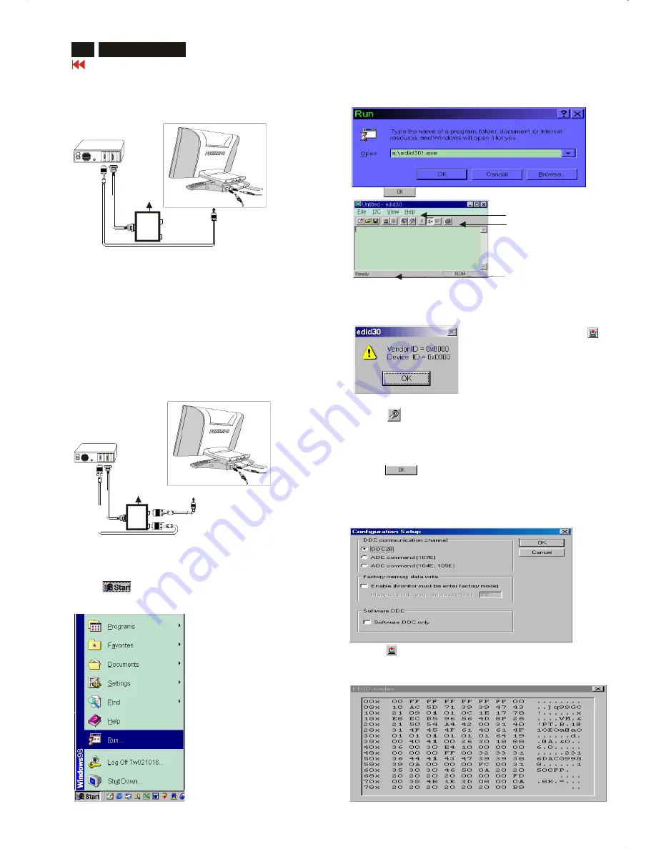
Step 1: Supply 8~12V DC power source to the Alignment box by
plugging a DC power cord or using batteries.
Step 2: Connecting printer cable and video cable of monitor as Fig. 4
Step 3: Run the EDID301.EXE program until the main menu appears.
This is for initialize alignment box.
Re-programming DDC IC
Step 1: After initialize alignment box, connecting all cables and box as
Fig. 5
Step 2: Follow the steps on DDC re-programming instructions to staring
re-programming.
Note: DVI-Dto D-Sub adapter can be removed if graphic card of PC with
a DVI-D interface connector.
DDC re-programming instructions
Start on DDC program
Start Microsoft Windows.
1. Insert the disk containing EDID301.EXE program into floppy disk
drive.
2. Click , choose Run at start menu of Windows 95/98.
Fig. 4
~
~
PC
T
o
printer
p
ort
(L
T
P1)
DC Power
8~12 V
Printer
Port
T
o
video
c
ard
To
Monitor
To PC
Re-programming Analog
Fig. 5
~
~
PC
T
o
video
c
ard
T
o
printer
port
(L
TP1)
DC Power
8~12 V
Printer
Port
To
Monitor
To PC
4. Click button. The main menu appears (as shown on Fig. 7).
Note:
If the connection is improper, you will see the following error
message before entering the main menu. Meanwhile, the
(read EDID) function will be disable. At this time, please make
sure all cables are connected correctly and fixedly, and the
3. At the submenu, type the letter of your computer's floppy disk drive
followed by :EDID301 (for example, A:\EDID301.exe,)
as shown in Fig. 6.
Fig. 7
Command bar
Tools bar
Status bar
Fig. 6
Loading DDC data from monitor
1.
Click icon on the tools bar to bring up the Configuration Setup
windows as Fig.8
2.
Select the DDC2B as the communication channel.
3.
Enable Factory memory data write function and fill in page address
F0 to the block.
4. Disable Software DDC function.
5.
Click button to confirm your selection.
Note: The Factory memory data write function will allow EDID301 to
rewrite serial numbers both Analog DDC IC and main EEPROM to
make sure both S/N are exactly the same. You may confirm the
function by checking the S/N at Product information of the OSD
menu after restarting the monitor.
6.
Click icon to read DDC EDID data from monitor. The EDID
codes will display on screen as following. (The EDID codes are
depend on the model.) Meanwhile, The status bar will indicate 00%
to 100% when reading.
Fig. 8
Rear view of 150X3M
3 1 2
Rear view of 150X3M
3 1 2
1=Power connector
2=DVI-D connector
3=D-SUB connector
1=Power connector
2=DVI-D connector
3=D-SUB connector
Summary of Contents for 150X3M
Page 35: ...35 150X3M LCD Go to cover page Colour Adjustment ...
Page 43: ......
Page 45: ......
Page 46: ......


