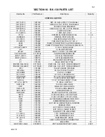
Phenix Technologies BK130 User Manual Download Page 37

BK-130 

16-2 

BK-130 PARTS LIST


Bubble No 

Part Number 

Description 

Quantity 


CONTROL SECTION (Cont’d)


GRN/YEL TESTLEAD 

30080018 

20 FT LARGE BLACK TEST LEAD 

20FT 

INPUT- CBL (120V) 

30110008 

30 FT 10/3 POWER INPUT CABLE 

INPUT- CBL (220V) 

30110028 

30 FT 14/3POWER INPUT CABLE 

TMR1 

1480120 

PANEL MOUNT DIG TIMER, OMEGA #PTC-13 

P2 

1151179 

OUTPUT TO TRANSFORMER RECEPTACLE 

P2 

1151185 

FEMALE CONTACT PINS 

INTER-MTR CBL (TX1) 

30160001 

20FT SIG / METERING INTERCONNECT CABLE 


HANDTRUCK


HANDTRUCK 

48660004 

HANDTRUCK ASSY  


LATCHES 

2371043 

CASE TO CART LATCHES 


HIGH VOLTAGE SECTION


BP-GROUND 

1351100 

BINDING POST 459 BLACK 

BP-GUARD 

1351104 

BINDING POST 459 WHITE 

BP-RETURN 

1351102 

BINDING POST 459 RED 

BP-SHORT BAR 

1351110 

SHORTING BAR 

D3001-4 

1780066 

13V TRANZORB 

MOV3001-3 (120 V) 

31107000 

METAL OXIDE VARISTOR ASSY 

MOV 3001-3 (220 V) 

1606110 

V275LA40 MOVISTOR 

R3001, 3002 

1748410 

200MEGS,1%,6W ROX4ST {SSX103} 

R3003, 3004 

1724400 

0.5W,200K,1% 

R3005 

1740199 

3W, 110

, 1% 

R3007 

1722570 

0.25W, 30K, 1% 

R3008 

1722087 

0.25W, 3.0K, 1% 

R3009 

1720600 

0.5W, 300 

, 1% 

R3010 

1740185 

10W, 30

, 1% 

SG3001-4 

1605110 

CGL90L,  SPARKGAP 90V 

T3001 

38342040 

GO2040 

TX1 

1151158 

TX1 CHASSIS CONNECTOR 

TX1 

1151170 

20 GUAGE PINS 

SPINNING 

2401340 

AL. SPNG, 3  “X12” FS12603 

LUNDEY 

2410125 

¼ - 20  LUNDEY 

CON CAPS 

1151196 

CONNECTOR CAPS 

– PROTECTIVE 

P3001 

1151178 

POWER CHASSIS CONNECTOR 

P3001 

1151183 

MALE PINS 

PCB 

1112232 

PCB 1223 

S.S. BALL 

2403120 

2” POLISHED STAINLESS STEEL BALL 


OPTIONAL ACCESSORIES 


STROBE LIGHT & 

POLE 

48660005 

TELESCOPING STROBE LIGHT ASSY. 

ALUMINUM COVER  

9607031 

ALUMINUM COVER  


Contact the Phenix Technologies Service Department Customer Service Coordinator for 
pricing of accessories.  

Summary of Contents for BK130

Page 1: ...130 USER S MANUAL AC DIELECTRIC TEST SET 600 SERIES Model Number BK130 36 Version 5 1 Phenix Technologies Inc 75 Speicher Drive Accident Maryland 21520 Copyright Phenix Technologies Inc Rev 2 9 2015 n...

Page 2: ...BK 130 DANGER...

Page 3: ...Test Equipment have been listed below for your reference Become familiar with your instrument before performing an actual test Know your work area check that all circuits are de energized and locked o...

Page 4: ...CTRICAL 4 OPERATIONAL VERIFICATION GENERAL TEST 5 GROUND GUARD RETURN CONNECTIONS 6 CALIBRATION 7 TROUBLESHOOTING 8 MECHANICAL MAINTENANCE 9 CHECKING OIL PURITY SPECIFICATIONS 10 TRANSPORTING STORAGE...

Page 5: ...ng Ambient Temperature 10 40 degrees C Output Termination 2 Polished Ball 36 kV 3 x 12 High Voltage Spinning 130 kV Metering Digital Output Voltmeter 3 Digit LCD Accuracy 0 8 of reading 2 of range Out...

Page 6: ...care in removing shipping materials so as not to damage unit 2 Perform visual inspection to determine if unit was damaged during shipment If there are any signs of physical damage such as dents scratc...

Page 7: ...BK 130 3 1 SECTION 3 CONTROLS AND INDICATORS Control Section FIGURE 3 1 TECHNOLOGIES PHENIX...

Page 8: ...sed Reset Lamp off Emergency Off Button pulled up Voltage Control at Zero 11 Voltage Control Adjusts Output Voltage and must be set at zero to turn High Voltage on 12 Currentmeter Range Selector 13 Ou...

Page 9: ...BK 130 3 3 CONTROLS AND INDICATORS FIGURE 3 2...

Page 10: ...st be connected from Ground to Return When the Jumper Clip is tied from Ground to Guard GRD any stray leakage currents associated with Ground or Guard will bypass the Current Meter and will not be mea...

Page 11: ...be sure the floor will be strong enough to support the unit If outdoor operation is to be used the site for the base must be capable of supporting the unit without any settling that would tilt the ass...

Page 12: ...30kV position 4 Connect the RETURN terminal at the base of the high voltage transformer to the meter receptacle on the boom using a coaxial lead Included in the optional accessory package 5 Connect th...

Page 13: ...BK 130 4 3 INITIAL SET UP ELECTRICAL Figure 4 1 TYPICAL TEST CONNECTIONS FOR CATEGORIES A B AERIAL DEVICES BONDING JUMPER BONDING JUMPER BONDING JUMPER EARTH or FACILITY GROUND HV TRANSFORMER CONTROLS...

Page 14: ...selector switch on the front panel is in the 130kV position 4 Connect the RETURN terminal at the base of the high voltage transformer to the chassis of the truck using the supplied lead 5 Connect the...

Page 15: ...Setup Electrical Figure 4 2 TYPICAL TEST CONNECTIONS FOR CATEGORY C AERIAL DEVICES BONDING JUMPER BONDING JUMPER BONDING JUMPER EARTH or FACILITY GROUND HV TRANSFORMER CONTROLS ISOLATION PADS UNDER TI...

Page 16: ...ront panel is in the 130kV position 4 Connect the RETURN terminal at the base of the high voltage transformer to the chassis of the truck using the supplied lead 5 Connect the power connector on the h...

Page 17: ...130 4 7 INITIAL SETUP ELECTRICAL Figure 4 3 TYPICAL TEST CONNECTIONS FOR CHASSIS INSULATORS EARTH or FACILITY GROUND HV TRANSFORMER CONTROLS ISOLATION PADS UNDER TIRES AND OUTRIGGERS CONTROLS CONTROL...

Page 18: ...will engage External Interlock loop must be closed Emergency Off switch must be closed mushroom button up Overload Reset Lamp must be off Voltage Control at Zero Start and Transformer Power Circuit Br...

Page 19: ...shorted output conditions Rated output currents are only available through a capacitive load of sufficient value Shorted current values should never exceed 50 of rated currents for the High Voltage Ta...

Page 20: ...t will require Set the dial to a high enough value to preclude false failure indications If this value is not known it is recommended that the dial be left in a higher setting 6 Press the HV On switch...

Page 21: ...ses the return current from ground to the RETURN terminal of the high voltage transformer 2 Guard Mode Use for boom and chassis insulator testing For test objects that can be fully isolated from groun...

Page 22: ...BK 130 6 2 GUARD GROUND RETURN CONNECTIONS Figure 6 1...

Page 23: ...ately rated High Voltage loads isolated from ground to the high voltage unit that will allow each full range current to be drawn at approximately 15 or higher output voltage This allows sufficient res...

Page 24: ...inimum 1 current trip level should be approx 18mA When dial is set to maximum 11 trip level should be approx 198mA b Set the Overload Trip potentiometer R15 on the front panel to 1 and the Current Ran...

Page 25: ...gency off has been pressed pull switch button up External interlock is open SX1 Voltage Control dial is not in zero start position Protection circuit Overload Trip is not Reset Transformer Power circu...

Page 26: ...range switch or wiring Faulty Circuit on PCB1257 5 Voltmeter inoperable Faulty TX1 interconnect cable Meter damaged No high voltage present at output bushing Damaged or inoperative Measurement Divider...

Page 27: ...oints for oil leakage If a leak is found retighten bolts to 5 ft lbs 3 Control Box Regulator Section At least once every year the control assembly should be removed for inspection of the regulator ass...

Page 28: ...ASTM D 877 test procedure If the oil tests lower than this consult Phenix Technologies Service Department for recommendations Generally for small portable transformers with small oil volumes draining...

Page 29: ...ir dielectric strengths of over 30 000 volts b Excellent Oxidation Stability Excellent oxidation stability and high resistance to sludging provide protection particularly where high temperatures are l...

Page 30: ...hibitor Content ASTM D2668 w w 0 30 max Interfacial tension ASTM D971 dynes cm 40 min Density 15 C ASTM D1298 g ml 0 91 max Viscosity 100 C ASTM D445 cSt 3 0 max Viscosity 40 C ASTM D445 cSt 12 0 max...

Page 31: ...ering to prevent damages during transport Prior to operation all insulating materials and bushings should be cleaned Protective caps should be in place on connectors 4 Optional cover for the transform...

Page 32: ...D TR M K K K TB X Intensite Diode Transisteur Thyristor Borne Ouvert Ferme Contact de SYMBOLE ZU SCHEMA SYMBOLES POUR SCHEMA DE CIRCUIT CIRCUIT DIAGRAM SYMBOLS Variable Resisitor Resistor Lamp Indicat...

Page 33: ...BK 130 13 1 SECTION 13 ELECTRICAL DIAGRAMS Drawing Number Description 9602130 120 V BK130 Electrical PCB 1257 9602132 220 240 V BK130 Electrical PCB 1257...

Page 34: ...include the serial number of the unit as well as the part number of the replacement part When your purchase order is received at our office a representative of Phenix Technologies will contact you to...

Page 35: ...ive for a recommendation Current prices may be obtained by contacting the Parts Ordering Department at Phenix Technologies PART NAME COMPUTER RECOMMENDED NUMBER QUANTITY LCD Meter KNS 3 Digit DMO 66T...

Page 36: ...WR CBL 10 2 20FT INTERCONNECT 1 POWER CBL 220V 30110029 PWR CBL 14 2 20FT INTERCONNECT 1 R15 1761098 10k 2W LINEAR 01F2644 1 R15 DIAL 1355910 46 15 010 DIAL 30 0 011 1 R15 KNOB 1355101 26 15 61 3 KNOB...

Page 37: ...066 13V TRANZORB 4 MOV3001 3 120 V 31107000 METAL OXIDE VARISTOR ASSY 1 MOV 3001 3 220 V 1606110 V275LA40 MOVISTOR 3 R3001 3002 1748410 200MEGS 1 6W ROX4ST SSX103 4 R3003 3004 1724400 0 5W 200K 1 2 R3...

Page 38: ...er Reason for Return Cause of Defect If Phenix Technologies Inc deems return of the part appropriate it will then issue an Authorization for Return If return is not deemed advisable other inspection a...

Page 39: ...s Manual are correct If there are concerns or comments as you have used this information Phenix Technologies appreciates any feedback Unit Serial Number Sect Page s Comment Please return to Phenix Te...

Reviews: