


BK-130
4-4
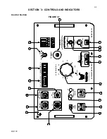
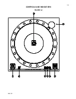
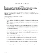
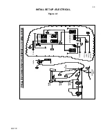
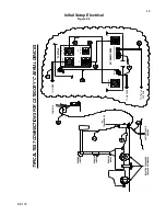
INITIAL SET-UP--ELECTRICAL
Connections for testing Category C Aerial Devices
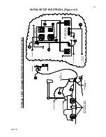
(REFER TO FIGURE 4-2
)
1. Connect the ground stud on the high voltage transformer to a good earth ground using the supplied
lead.
2. Connect the ground stud on the high voltage transformer to the ground stud on the control cabinet
using the supplied lead.
3. Connect the HV (130kV) output terminal on top of the high voltage transformer to the bucket of the
truck under test using a piece of wire. (Included in the optional accessory package) Verify that all
metal in the bucket is bonded together and connected to the high voltage lead using bus wire or clip
leads (Included in the optional accessory package). Make sure that the tap selector switch on the
front panel is in the 130kV position.
4. Connect the RETURN terminal at the base of the high voltage transformer to the chassis of the truck
using the supplied lead.
5. Connect the power connector on the high voltage transformer to the mating connector on the control
cabinet using the supplied cable.
6. Connect the control/metering connector on the high voltage transformer to the mating connector on
the control cabinet using the supplied cable.
7. Connect input power cable to controls. Do not connect to power source until setup is complete.
8. This connector has a jumper installed that can be removed to connect an external safety switch
(Included in the optional accessory package).
NOTES:
Other jumpers to bypass chassis insulators, pivot points, knuckles, joints, etc. are usually required.
Truck must be isolated from ground for testing (Isolation pads included in optional accessory package)


