


BK-130
5-1
SECTIION 5: OPERATIONAL VERIFICATION PROCEDURE
1. Make sure that Main Power Circuit Breaker on the Control Panel is in OFF position.
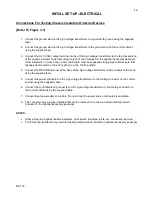
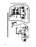
2. Make sure that all electrical connections have been properly made between the Controls and High Voltage
Unit, including grounds. Remove Ground from HV Transformer output if it is grounded. There is to be no
connection to the high voltage outputs at this time. There must be adequate clearance from the High
Voltage Unit to allow voltage to be raised safely.
3. Place currentmeter in RTN mode. (Connect jumper of RETURN/GND/GUARD binding posts between
RETURN and GND)
4. Connect Main Input Power Cable to Controls and to Power Source. Switch the Main Power Circuit
Breaker on the Control Panel to On position. Main Power indicator lamp should illuminate. Check that the
Transformer Power Breaker is on, Emergency Off button is pulled up, Voltage Control is at Zero, Reset
Lamp is Off, and EXT INTLK CKT is complete or has shorting jumper in place. HV Off lamp should be
illuminated.
5. Press HV On switch. Indicator lamp should illuminate. Press the HV Off switch. HV On indicator lamp
should extinguish and HV Off / Ready lamp should illuminate.
NOTE:
The following conditions
must be
met before High Voltage will engage: External Interlock loop
must be closed, Emergency Off switch must be closed (mushroom button up), Overload Reset Lamp must
be off, Voltage Control at Zero Start, and Transformer Power Circuit Breaker on.
6. Set Measurement Divider Switch to 130 kV / 50 mA
7. Press the HV On switch.
8. Manually raise the Voltage Control dial on the Control Panel to approximately 50 (50%). Voltmeter should
indicate voltage change, and show approximately 55 to 65 kV.
9. Select 36 kV/ 180 mA on Measurement Divider Selector Switch. At 50 on Voltage Control Dial, voltmeter
should read approximately 16 to 20 kV.
10. Return Voltage Control to Zero. Press HV Off switch.
11. Turn Main Power Circuit Breaker off and connect a short between the 36kV High Voltage Output and
Ground. Measurement Divider Switch is to be set at 36 kV / 180 mA.
12. Set Overcurrent Trip to low (1) setting.
13. Turn Main Power Circuit Breaker on. Press HV On switch and slowly raise voltage with the dial on the
Control Panel. Output Current Meter will indicate, and at approximately 10% of output current rating, the
High Voltage will trip off and the Overcurrent Indicator Lamp will illuminate. With the front panel Overload
Selector Switch set at 36 kV/180 mA, the trip point should be at approximately 17.2 mA. Return Voltage
Control to zero and turn off Main Power Circuit breaker.
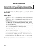
WARNING
:
This equipment should only be used by personnel familiar with High Voltage Testing and Safety
Procedures.


