background image

iX Controller MK 5 Installation and Operation Guide 
Appendix A. Configuring the Applanix GNSS 


Page 30 of 36 


A.2.4


INS 

Note 

Configure the INS if you are using the IMU located inside the iX Controller MK 5. When using an external 
IMU, see Section A.2.5 - External IMU. 


1.


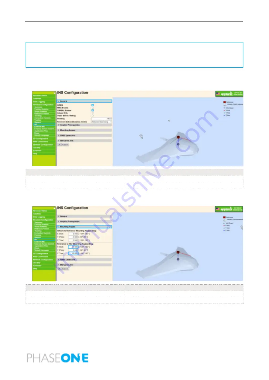
In the menu, under Receiver Configuration, click INS, click General, and configure the outlined 
parameters as following: 


Parameter 

Setting 

GAMS 

Unselected. 

GIMBAL Enable 

Selected 


2.


Click Mounting Angles and configure the outlined parameters as shown following. 


Parameter 

Setting 

X [Roll] 

-90.000 

Z [Roll] 

90.000 


3.


Click OK. 

4.


Reboot receiver for the changes to take effect. 

Summary of Contents for iX MK 5

Page 1: ...iX Controller MK 5 Installation and Operation Guide ...

Page 2: ...without further notice Trademarks All trademarks or registered trademarks are the property of their respective owners Contact Support You can contact Phase One Technical Support directly by creating a support case at https industrial phaseone com Support aspx Visit https geospatial phaseone com for additional information Copyright 2022 Phase One All Rights Reserved Doc No 80077000 Rev 5 0 3 iX Con...

Page 3: ...nd Peripherals 11 4 1 iX Controller MK 5 Power Cable P N 70348000 11 4 2 iX Controller iX Camera Power Cable P N 70364000 12 4 3 iX Controller MK 5 to Camera I O Cables P N 70378000 13 4 4 iX Controller MK 5 to Camera USB 3 0 Cables 14 4 5 Monitors 14 4 6 Keyboard and Mouse 16 4 7 External IMU 17 4 8 PPS Output 18 5 Powering up the iX Controller MK 5 19 6 iX Controller MK 5 Storage 20 6 1 Disk Man...

Page 4: ...ing SSD Drives 25 Appendix A Configuring the Applanix GNSS 26 A 1 Configuring Data Logging 26 A 2 Configuring the Receiver 28 A 2 1 Tracking 28 A 2 2 Position 28 A 2 3 General 29 A 2 4 INS 30 A 2 5 External IMU 32 A 2 6 External Sensor Control 33 A 3 Configuring I O Ports 34 A 3 1 Serial COM1 Gimbal Settings 34 A 3 2 Serial COM2 Camera 35 A 3 3 TCP 5018 NMEA for iX Flight 36 ...

Page 5: ...planix GNSS 1 2 Applicable Documents Item Manual Phase One iX Controller How to Connect Remotely to iX Controller Phase One iX Capture iX Capture User Guide Phase One iX Flight iX Flight User Guide Applanix POS AV V6 and V7 POS AV V6 and V7 Installation and Operation Manual PUBS MAN 004809 Revision 13 Date 30 November 2020 1 3 List of Terms and Abbreviations Term Abbreviation Description DP Displa...

Page 6: ...rrier key 40900718 1 5 mm hex screwdriver 70306000 iX Camera to External GNSS Control Cable 70348000 Aircraft to iX Controller MK 5 power cable Note If the iX Controller MK 5 is supplied as part of system with a stabilizer a different power cable is supplied as detailed in the guide for that system 70364000 iX Controller MK 5 to camera power cable 70378000 iX Controller MK 5 to camera I O cable ...

Page 7: ... 73275000 iX Controller MK 5 76004600 SSD frame for assembly in post processing host computer 86718900 USB drive with documentation 86720500 iX Products warranty certificate 2 1 Product Identification To enable support for your system you must record the serial number mark on the rear panel of your unit ...

Page 8: ...ft power supply A high capacity data storage SSD tray factory provided with two 1 TB SSD drives can be easily accessed or removed for rapid download of image and telemetry data Figure 1 iX Controller MK 5 Front Panel 1 SSD carrier eject button 2 SSD carrier keylock 3 SSD drive LEDs 4 SSD drive carrier 5 AUX2 power ports x3 6 AUX2 Power LED 7 AUX1 Power LED 8 AUXILIARY Power LED 9 MAIN Power LED 10...

Page 9: ... 32 VDC Maximum current 20 A The Auxiliary power circuit breaker controls all power to the six AUX1 and AUX2 power ports It also controls power to the internal GNSS Inertial The output voltage from all six power ports is the same as the incoming voltage from the iX Controller MK 5 power source Each set of power ports AUX1 and AUX2 can be software controlled using iX Capture Power consumption is as...

Page 10: ...ontrol over the cameras installed on the iX Controller MK 5 aerial system It enables the operator to easily monitor and control every aspect of aerial digital data acquisition using the operator monitor iX Capture enables you to capture monitor and process images in a fast flexible and efficient workflow iX Capture is pre installed on iX Controller MK 5 For detailed information on installing iX Ca...

Page 11: ...5 System Power Requirements Parameter Requirement Voltage 24 32 VDC Maximum current 20 A Table 3 and Figure 3 show the pinout for the aircraft to iX Controller MK 5 power cable Table 3 Aircraft Power Cable Pinout Wire Pin Voltage Red 1 28 VDC Black 2 0 VDC Figure 3 Aircraft Power Cable Pin Designation Note Before connecting the system power cable to the aircraft power outlet make sure you have ver...

Page 12: ... Camera Power Cable P N 70364000 The iX Controller iX Camera power cable provides power to the camera To connect iX Controller iX Camera power cables 1 Connect one end of the iX Controller iX Camera power cable to an iX Controller MK 5 AUX1 or AUX2 port Figure 5 iX Controller iX Camera Power Cable Connection to iX Controller MK 5 Note It is recommended to connect all cameras to the same set of pow...

Page 13: ...he camera In addition it provides metadata to the camera To connect the iX Controller MK 5 to camera I O cables 1 Connect one end of the iX Controller MK 5 to camera I O cable to the iX Controller MK 5 I O port Figure 6 Camera I O Cable Connection to iX Controller MK5 2 Connect the other end to the camera left I O port Note For I O connections on additional cameras use a Phase One camera to camera...

Page 14: ...crews securing the left USB 3 0 cable bracket to the iX Controller MK 5 2 Connect up to six USB cables as required to the left USB 3 ports 3 Place the USB 3 0 cable bracket in place on the iX Controller MK 5 and secure all four screws using the 1 5 mm hex key 4 Connect the other end of each USB 3 cable to a Phase One aerial camera 4 5 Monitors Phase One recommends ordering and using the pilot and ...

Page 15: ...wer and video ports video cable includes USB signal 2 Connect the cable end with 3 connectors to the iX Controller MK 5 AUX2 power port an HDMI port and one of the Camera USB 3 ports To connect the operator monitor 1 Connect one end of the cable to the operator monitor power video and USB ports 2 Connect the other end of the cable to the iX Controller MK 5 AUX2 power port DP port and one of the Ca...

Page 16: ...ashers and set them aside 3 Connect the keyboard and mouse cables to the USB ports 4 Use a 2 5 mm hex key to reattach the cable bracket front plate to the cable bracket bottom plate using the screws and washers you set aside in Step 2 The front plate should secure the cable hoods Note If the length of the cable hoods prevent you from securing the cable bracket front plate to the cable bracket bott...

Page 17: ... iX Controller MK 5 3 Mount the cable bracket bottom plate to the iX Controller MK 5 using the holes near the bottom plate edge 4 7 External IMU If you are using an external IMU see Section 3 2 Configuration Options you must connect it to the iX Controller MK 5 using the cable supplied with the external IMU For USB cables with short hoods For USB cables with long hoods ...

Page 18: ... the PPS Output connector on the iX Controller MK 5 rear panel Table 4 shows the pinout for the iX Controller MK 5 PPS output cable Table 4 iX Controller MK 5 PPS Output Cable Wire Pin Voltage Description Orange 1 PPS_OUT PPS Pulse Per Second output is the signal that indicates the integer epoch of UTC GPS time It is a 1 msec wide active low 5 V pulse with a 5 µsec fall time from buffer that can d...

Page 19: ...h the Main circuit breaker The MAIN Power LED comes on and the iX Controller MK 5 powers up 2 When the Windows 10 login window appears log in using the following credentials User name user No password required Note To remotely login to the iX Controller MK 5 see How to Connect Remotely to iX Controller available for download at https industrial phaseone com downloads guides aspx ...

Page 20: ...en Solid The drive is powered on Drive activity Amber Blinking The drive is being accessed by the iX Controller MK 5 The drives are assigned the following drive letters D top drive E bottom drive 6 2 Locking the Carrier Note The carrier must be locked with the SSD carrier key for the iX Controller MK 5 to recognize the drives To lock the carrier in the SSD drive bay frame Note The SSD carrier key ...

Page 21: ...n the iX Controller MK 5 2 Insert the SSD carrier key into the SSD carrier keylock and turn it 90 counterclockwise 3 Push the SSD carrier eject button once to release the button and again to eject the carrier from the frame 4 Gently remove the SSD carrier from the iX Controller MK 5 6 4 Inserting the SSD Drive Carrier To insert the SSD drive carrier into the iX Controller MK 5 1 Shutdown the iX Co...

Page 22: ...der System Settings 7 2 Using iX Capture 1 On the operator panel desktop double click iX Capture 2 Follow instructions for setup and use of iX Capture as described in the iX Capture User Guide on the USB drive provided with iX Controller MK 5 and available for download at https industrial phaseone com downloads guides aspx 7 3 Using iX Flight 1 If you purchased a license for iX Flight on the opera...

Page 23: ... Operation Guide 8 Shutting Down the iX Controller MK 5 Page 23 of 36 8 Shutting Down the iX Controller MK 5 To shut down the iX Controller MK 5 1 Perform a standard Windows 10 shutdown 2 Pull out the Main and Auxiliary circuit breakers ...

Page 24: ...iX Controller MK 5 MAIN Power LED is on but Windows 10 does not appear Pull out the Main circuit breaker and push it back in The HW trigger is grayed out GPS GUI windows does not come up Pull out the Auxiliary circuit breaker and push it back in then restart iX Capture GPS does not lock onto satellites Check antenna cable Pull out the Auxiliary circuit breaker and push it back in ...

Page 25: ...d 500 MB S Drive capacities can be different To replace the SSD drives 1 Remove the carrier from the iX Controller MK 5 see Section 6 3 Removing the SSD Drive Carrier 2 Remove both cover screws at the rear of the carrier 3 Slide the carrier out from the carrier cover 4 Remove all screws securing the SSD drives to the carrier 5 Replace the SSD s in the carrier 6 Secure the SSD s to the carrier 7 Sl...

Page 26: ...ingly Refer to this appendix if you need to reset the GNSS to the original Phase One configuration 1 Verify that a monitor keyboard and mouse are connected to the iX Controller MK 5 as described in Section 4 Connecting Cables and Peripherals 2 Power up the iX Controller MK 5 as described in Section 5 Powering up the iX Controller MK 5 3 Click the Applanix icon in the Windows taskbar Note In this s...

Page 27: ...ge 27 of 36 2 Configure the parameters as shown following Parameter Setting Enable Selected Schedule Continuous Measurement Interval 0 1 Sec Position Interval 0 01 Sec Log Received Corrections Selected Log SBAS Data Selected File System Internal Path Style Flat Name Style YYYYMMDDhhmm 3 Click OK ...

Page 28: ... 1 Tracking 1 In the menu under Receiver Configuration click Tracking and configure the outlined parameter as shown following Parameter Setting SBAS L1 C A Unselected 2 Click OK A 2 2 Position 1 For fixed wing aircraft in the menu under Receiver Configuration click Position and configure the outlined parameter as shown following 2 Click OK ...

Page 29: ...nix GNSS Page 29 of 36 A 2 3 General 1 In the menu under Receiver Configuration click General and configure the parameters as shown following Parameter Setting Enable Shared Port Serial 3 Event 1 On Off Enable Event 1 Slope Negative 1PPS On Off Enable 1PPS Always On Selected 2 Click OK ...

Page 30: ...ing an external IMU see Section A 2 5 External IMU 1 In the menu under Receiver Configuration click INS click General and configure the outlined parameters as following Parameter Setting GAMS Unselected GIMBAL Enable Selected 2 Click Mounting Angles and configure the outlined parameters as shown following Parameter Setting X Roll 90 000 Z Roll 90 000 3 Click OK 4 Reboot receiver for the changes to...

Page 31: ...e 31 of 36 Note When measuring the IMU lever arm use the iX Controller MK5 right aft screw head center as a reference point The following measurements are from the screw head center to the internal IMU measurement center in a controller coordinate system shown below X 26 01mm Y 69 9 mm Z 47 14 mm ...

Page 32: ...em Reference to IMU Lever Arm Reference to IMU Mounting Angles Parameter Setting External IMU Enable Selected External IMU Nav Solution Selected External IMU Type Select the external IMU in use Reference to Primary GNSS Lever Arm in VEHICLE frame Enter the values as measured in the aircraft Reference to IMU Lever Arm in REFERENCE frame Enter the values relevant for the system you are using Referen...

Page 33: ...er Configuration click External Sensor Control and configure the outlined parameter as shown following Note The following configuration is for controlling the SOMAG stabilizer through Applanix GNSS Parameter Setting Enable YDC Yaw Drift Correction Selected Follow Mean Track or Follow Desired Heading Select the required option depending on your mode of operation to obtain the heading from the fligh...

Page 34: ...ntrolled by iX Flight 1 In the menu under I O Configuration click Port Configuration and configure the parameters as shown following Parameter Setting GIMBAL GIM01 for CSM40 DSM400 stabilizers controlled by iX Flight to obtain gimbal data recorded in To4 files 2 Click OK For Systems Using SOMAG GSM 4000 Stabilizer 1 In the menu under I O Configuration click Port Configuration and configure the par...

Page 35: ...Appendix A Configuring the Applanix GNSS Page 35 of 36 A 3 2 Serial COM2 Camera 1 In the menu under I O Configuration click Port Configuration and configure the parameters as shown following Parameter Setting EVT On EN1 On NMEA Legacy Selected 2 Click OK ...

Page 36: ...iguring the Applanix GNSS Page 36 of 36 A 3 3 TCP 5018 NMEA for iX Flight 1 In the menu under I O Configuration click Port Configuration and configure the parameters as shown following Parameter Setting GGA 20 Hz GSA 20 Hz VTG 20 Hz EVT On PASHR 20 Hz EN1 On 2 Click OK ...

Reviews: