background image

70Xi Cold Flow Properties Laboratory Analyzer   


         User Guide 


24 

A p p e n d i x   B .    
C l e a n i n g   &   R o u t i n e   M a i n t e n a n c e    
 

Cleaning the LED Touch Screen and External Surfaces of the Analyzer 

The screen protector shields the touch screen surface from dirt and spills while maintaining the screen’s 
responsiveness and functionality. The screen protector film should be replaced every 6 months.  

Clean the analyzer’s LED touch screen using a soft, lint-free cloth and lens cleaner solution containing a 
mixture of alcohol and water. Gently wipe down the screen until any visible fingerprints, smudges, dust or 
other signs of contaminants are gone.  

Clean the external surface of the analyzer with a soft, damp cloth. 


Routine Maintenance Schedule:  

Every 300 Test Runs (or more frequently if necessary) 


Replace Desiccant 

Every 6 months: 


Replace Screen Protector 

Replace 12 months:   


Replace Dryer Bottle O-ring  


Replace Lid O-Ring  


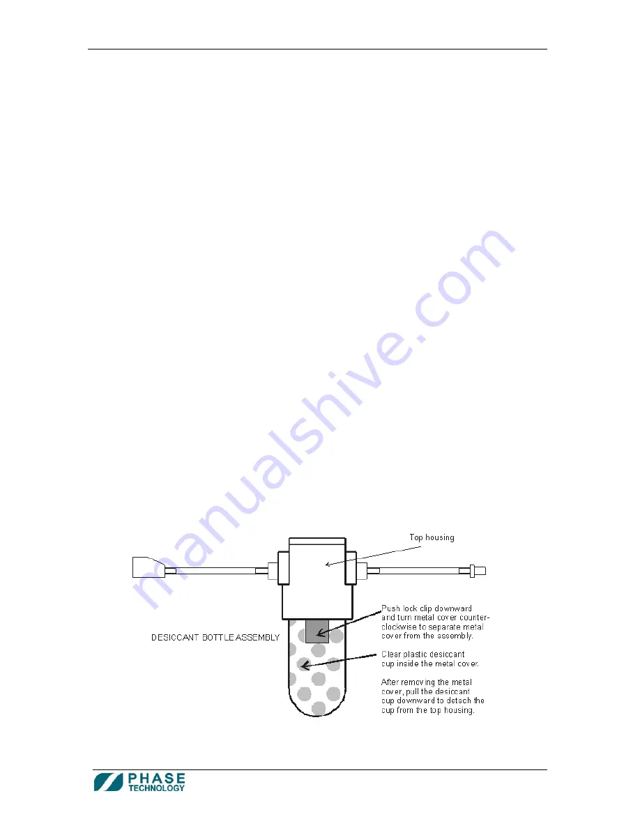
How to Replace the Desiccant: 

1.


Turn off power to analyzer.  

2.


Disconnect dryer bottle from back of analyzer by pressing the spring plates of both quick-connect 
fittings and pulling them to separate.  

3.


Keep the dryer bottle vertical (upright). Push the lock clip of the desiccant cup protector 
downward and turn it to the left (counterclockwise) to separate the metal cover from the 
assembly.   

4.


Pull the desiccant cup downward to separate the bowl from the top housing. 


Summary of Contents for 70Xi-SS

Page 1: ...70Xi SS COLD FLOW PROPERTIES SINGLE SHOT ANALYZER SYSTEM USER GUIDE ...

Page 2: ...rding or otherwise without the prior written permission of this copyright holder Phase Technology The following document contains proprietary information of Phase Technology These contents are confidential and any disclosure to persons other than the officers employees agents or sub contractors of the owner or licensee of this manual without the prior consent of Phase Technology is strictly prohib...

Page 3: ...est Results 11 Section 7 How to View Phase Plots 11 Section 8 How to Use QC Chart Limits Sample Specifications and Trending of Test Results 12 Section 9 How to Change User Level Access 16 Section 10 How to Shut Down and Restart the Analyzer 18 Section 11 How to Use the Analyzer s Connectivity Features 18 Appendix A How to Use DrySac 23 Appendix B Cleaning Routine Maintenance 24 Appendix C FAQ Cali...

Page 4: ...rol Panel BOLD ALL UPPER CASE CAPITALS Buttons on the touch screen RUN Text in parenthesis Message displayed on screen Run Count xxx Text in bold blue italics Refers to another chapter or section in User Guide please refer to the Analyzer Options section NOTES CAUTIONS AND WARNINGS Important information and alerts are brought to your attention with the following conventions and icons NOTE Indicate...

Page 5: ... transfer tube 1 8 Teflon tube with stainless fitting on one end and brass fitting on other end from the Sample Injection Port Assembly stainless steel fitting to the analyzer SAMPLE IN port brass fitting Connect the supplied 1 8 Teflon tube with brass fitting on one end and no fitting on other end from the analyzer SAMPLE OUT port to a user supplied waste bottle 7 Connect the power cable to the b...

Page 6: ...en Fig 1 The analyzer returns to this screen whenever the HOME button is pressed Figure 1 Home screen a The Sample Cup temperature Optics light Signal and Run Count are displayed at the top of the screen A set of Favorites buttons is listed on the right hand side See sections 3 How to Run Tests Using Pre defined Favorites and 5 How to Create and Modify Favorites The main area in the middle is init...

Page 7: ...h test sample Make sure the vial is filled up all the way to the neck NOTE The analyzer automatically determines the amount of current sample up to 30 mL needed to rinse and clean the previous sample Error messages such as No sample flow might occur if insufficient sample is found For best results it is important to fill the vial to its neck 3 Lift the probe of the Sample Injection Port Assembly b...

Page 8: ...1 To start a run using a predefined test setting press and hold for one second one of the favorite buttons see section 5 How to Create and Modify Favorites 2 During the test the LED on the test chamber lid will be red indicating that the chamber is running and the lid should not be opened H o w t o R u n T e s t s U s i n g P r e d e f i n e d F a v o r i t e s 3 ...

Page 9: ...settings such as the Sample ID Run Mode and Sample Type Temperature unit etc can be viewed or modified from the Settings window Fig 2 The Settings window can be opened by tapping a favorite or pressing the arrow button beside the Favorites window 2 Changing the analyzer settings requires permission to be enabled by the administrator see section 9 How to Change User Access Levels Figure 2 Settings ...

Page 10: ... or pour point The analyzer will flush the sample through the system 4 Press the RUN button to start a test run using the current settings 5 Press the ADD TO FAVORITES button to save the current settings as a new favorite The existing Sample ID will become the name of the new favorite 6 Press the HOME button to close the Settings window and return to the Home screen 7 The Settings window can also ...

Page 11: ...icated by a note icon Press and hold the icon to read the note 4 To view the corresponding phase plot of a result press the desired row in the table of results see section 7 How to Review Phase Plots for more information on phase plots 5 Press the HOME button to return to the Home screen When the 70Xi analyzer completes a test run a phase plot is displayed on screen with the final test result See ...

Page 12: ...and the sample movement graph 1 QC Samples and Control Limits a All QC samples are identified with the QC prefix in the sample ID Press SET AS QC in the Settings window see section 4 How to Change Test Settings to assign the current sample as a QC standard i e analyzer will automatically add the QC prefix to the current sample ID b In order to enter or auto calculate control limits there must be a...

Page 13: ...the HOME button to save the control limits and return to the Home screen k Whenever the test result of a QC sample exceeds the control limits a pop up window will appear with the message The last QC test exceeded the control limit requirements This pop up window will appear each subsequent time the analyzer starts a non QC test under the same run mode that has failed the previous QC test until one...

Page 14: ...Level Access d To assign specification limits press ANALYZER OPTIONS from the Home screen e On the Analyzer Options screen press SAMPLE SPECIFICATIONS f Select the sample in the list box that you wish to enter or modify the specification limits g Select the Temperature Unit C or F at the top of the window h Enter the Maximum Specification Minimum Specification and or Expected Value for the corresp...

Page 15: ...st box or enter the desired sample ID to generate the control chart or trend graph for that sample e Once the control chart or trend graph is generated the phase plot for any result on the chart or graph can be opened simply by touching the data point on the graph f The QC Control Limits and Sample Specifications button accesses those screens directly from the trend graph screen for administrators...

Page 16: ...sword protected and has access to all available features Administrators can also configure access permissions of certain features for the User group c Factory reserved for factory use only 2 To change the current user level press the ACCESS button at the lower left corner The Access screen appears see Fig below 3 Select either USER or ADMINISTRATOR 4 To setup or modify the password at the Administ...

Page 17: ... set up the analyzer will prompt for the password each time the user level is switched to Administrator 5 To modify User group permissions a Switch user level to Administrator b From the Home screen press ANALYZER OPTIONS button c Press USER LEVEL ACCESS d Select either Allow or Deny for access at the User level 1 Favorites Changes adding deleting or organizing favorites 2 Test Settings Changes mo...

Page 18: ...lyzer press the ACCESS button and then press the SHUT DOWN button 2 To restart analyzer press the ACCESS button and then press the RESTART button 1 Data Download via USB a To download data from the analyzer to a USB memory stick simply insert the USB memory stick to the front USB port beside the power button The USB Download screen will automatically appear see figure on next page 2 H o w t o U s ...

Page 19: ...Spreadsheet programs like MS Excel can be used to display the data and do further analysis 3 DETAIL PHASE PLOT DATA OF INDIVIDUAL TESTS DAT This option will open another window for user to select individual tests and phase plot data Phase plot data files can be opened and viewed on an external PC with Phase s LTB program 4 BACKUP SOFTWARE Before upgrading to newer software it is recommended to use...

Page 20: ...pleted simply remove USB memory stick from the USB port to close the USB Download screen 2 LIMS optional a LIMS connection is through either the RS232 Serial Port B analyzer or the Ethernet port both located at the back of the analyzer b For serial connection to PC set the following Baud rate 38400 Data 8 bit parity none Stop 1 bit Flow control none c To setup the location of the results file for ...

Page 21: ...nnection d To setup automatic LIMS output after each test 1 Switch user level to Administrator see section 9 How to Set User Level Access 2 From the Home screen press ANALYZER OPTIONS button 3 Press SETUP 4 On the Setup screen select either OFF or ON for Automatic LIMS Output 5 Press the HOME button to save the settings and return to the Home screen e To test LIMS 1 From the Home screen press ANAL...

Page 22: ...ings and return to the Home screen d To test the printer 1 From the Home screen press ANALYZER OPTIONS button 2 On the Analyzer Options screen press PRINTER TEST A default result will be printed 4 Barcode Scanner optional a The barcode scanner can be connected to one of the two USB ports at the back of the analyzer b To scan a barcode as the sample ID simply press SCAN BARCODE beside the Sample ID...

Page 23: ...n testing jet fuels it is recommended that samples be dried prior to beginning the test run To treat the sample place a fresh DrySac in an empty clean vial Fill the vial with enough sample to completely cover the DrySac between 5 10 mL Put the cap on the vial and swirl the contents a few times Let the DrySac sample dry for a few minutes Sample is now ready to be pipetted into the chamber DrySac ca...

Page 24: ...rints smudges dust or other signs of contaminants are gone Clean the external surface of the analyzer with a soft damp cloth Routine Maintenance Schedule Every 300 Test Runs or more frequently if necessary Replace Desiccant Every 6 months Replace Screen Protector Replace 12 months Replace Dryer Bottle O ring Replace Lid O Ring How to Replace the Desiccant 1 Turn off power to analyzer 2 Disconnect ...

Page 25: ...sure that the o ring track is clean and void of any broken desiccant debris You only need to replace the dryer bottler o ring on an annual basis 6 Get new pack of desiccant cut across corner to open 7 Cover the down pipe using a piece of adhesive tape or a finger 8 Refill bottle with new desiccant Do not fill past 1 2 1 2 cm from the top of the bowl Use the fill to this line mark on the bottle to ...

Page 26: ...circulate through the purge system and will damage vital components and void the warranty Only use desiccant supplied by Phase Technology Replace the dust filter ring every 5 desiccant packages or approximately every 1500 runs Replace the dryer bottle o ring once yearly or if it is damaged Join the dryer bottle connection ends together if the dryer bottle is not connected to the analyzer This prev...

Page 27: ...isons between a test instrument and defined international standards all having stated uncertainties Phase Technology analyzers are calibrated during the manufacturing process and are traceable to ASTM standards ASTM standards are well recognized and have been quantified in accepted round robin tests What are the benefits of maintaining current calibrated equipment Maintaining an up to date calibra...

Page 28: ...th performance checks and inspection of internal components to prevent potential problems before they develop What are the benefits of having on site or service center preventive maintenance Preventive maintenance ensures that your analyzer is running optimally and helps identify possible problems before they cause bottlenecks in workflow assurance that results are consistent and repeatable increa...

Page 29: ...on top of a previous good QC phase plot will immediately show if and how the wax crystal behavior is different between the two tests One of the most common causes for a failed test is sample contamination sample contamination can be easily identified by observing a dragging tail on the phase plot when compared through overlay with a known good test run Cloud Point Cloud point is the temperature at...

Page 30: ... Phase Technology s 70Xi analyzer cools the sample relatively quickly until wax crystals begin to form On a freeze point phase plot this can be seen as the blue line moves from left to right As the crystals form the baseline rises After a sufficient number of crystals are present the sample is warmed until they all disappear This warming phase is shown in green on the phase plot Freeze point can b...

Page 31: ...disturbances in the sample The 70Xi Analyzer s optical sensors take a sequence of pictures to detect this movement Absence of movement indicates that the pour point has been reached The phase plot shows temperature on the horizontal axis and signal on the vertical axis The signal is an indication of the amount of movement experienced by the sample As the sample is cooled green bars show the magnit...

Page 32: ...customs Warranty Protection Opening a Phase Technology analyzer without authorization voids the warranty Only trained Phase Technology service technicians are properly equipped to make repairs to our analyzers How it Works Phase Technology Customer Service Process 1 Customer sends email to customer_service phase technology com to report a problem Phase Technology Customer Service responds directly...

Page 33: ... the costs of such return will be borne by the customer and those of delivering the repaired or replacement Products to the customer will be borne by Phase Technology The Company s sole liability hereunder shall be to repair or replace any product which proves to be defective In no event shall the Company be liable for any special incidental consequential indirect or other similar damages arising ...

Reviews: