


(6)Cylinder and piston
A.Trouble shooting
B.The Operation notice
C.Data
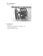
D.Dismaniling cylinder, piston
E.Installing cylinder, piston
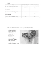
C.Data (150CC)
Part name /description
Standard value
( mm )
Limit of use
( mm )
Bore
57.490~57.510 57.600
Curve
- 0.005
Cylindrility
- 0.005
Cylinder
Roundness
- 0.005
lst ring
0.03~0.07
0.10
Clearance b/w Piston
and
Piston ring
2
nd
ring
0.02~0.06
0.10
lst ring
0.10~0.25
0.50
2
nd
ring
0.10~0.25
0.50
Clearance of cutting
section
side ring
0.2~0.7
---
Piston outer diameter
57.470~57.490 57.400
Measuring location of piston outer dia.
Down to 5 mm from the
piston skirt
---
Clearance b/w piston and cylinder
0.025~0.035 0.10
Piston/
Piston ring
Piston pin hole inner dia
15.006~15.012 15.030
Piston pin outer diameter
14.990~14.992 14.96
Clearance between piston and piston pin
0.020~0.017 0.025
Connecting rod small end inner dia
15.010~15.028 15.060
Summary of Contents for ALLORO 125
Page 1: ...Manufactured by Motive Power Industry Co Ltd ...
Page 17: ...C Chassis appearance 1 Apply oil 1 2 2 Apply grease 3 4 5 6 7 8 1 2 3 4 5 6 7 8 ...
Page 18: ...D Wheel bearing Final transmission mechanism gear oil Speedometer gear clean grease ...
Page 62: ...7 Remove the start idle gear fixing plate 8 Take off the idle gear ...
Page 82: ... 7 Crankcase Crankshaft A Disassembling diagram ...
Page 94: ... 1 Lubrication System ...
Page 118: ... 7 A C Generator A Dismantling AC generator B Installing AC generator ...
Page 132: ......
Page 164: ... 3 Recharge system A Recharge system diagram for M2 50 ...
Page 165: ...B Recharge system diagram for M2 125 150 ...
Page 170: ...46 Wiring diagram for M2 50 ...
Page 171: ...47 Wiring diagram for M2 125 150 ...
Page 172: ...48 Wiring diagram for M2 150 4V ...
Page 173: ...49 Wiring diagram for M2 200 ...
Page 174: ......
Page 175: ......
Page 176: ...50 Wiring diagram for M2 250 ...
Page 192: ...1 6 3 Electric system Carburetor model electric General maintenance Engine Management System ...
Page 201: ...10 G MAX 200 220 Specified engine oil synthetic 1000ml ...
Page 210: ...19 Ignition coil Dismantle the right lower cover You can see the ignition coil clearly ...
Page 215: ...1 6 5 Engine Management System EMS ...
Page 216: ...2 EMS index PGO 2nd stage EMS structure EMS units EMS diagnostic ...
Page 217: ...3 Feature of PGO 2nd stage EMS feature 1 small light 2 integrity 3 accuracy 4 simple ...
Page 220: ...6 EMS units ...
Page 221: ...7 噴油嘴 Throttle position sensor Intake pressure sensor injector Idle Speed Controller ...
Page 223: ...9 ECU Electronic Control Unit Topple snsor Second air solenoid ...
Page 224: ...10 Important PIN no of ECU ECU PIN 1 PIN 18 PIN 19 PIN 36 PIN ...
Page 235: ...21 Oxygen sensor W heater 12V 2 couple 8Ω Gr ground B output ...
Page 240: ...26 Fuel pump R B output 12V B ground R B B voltage 12V resistance 1KΩ ...
Page 243: ...29 ISC Idle Speed Control W ISC A R B ISC B G ISC B Gr ISC A ISC unit R A A 80Ω B B 80Ω ...
Page 248: ...34 EMS fuses 7 5A 10A 5A 1A 10A 15A ...
Page 250: ...36 6 6 EMS diagnostic ...
Page 251: ...37 part no S320840G01 name quick diagnostic Quick diagnostic ...
Page 254: ...40 part number S320891G01 name software adapter PC diagnostic software adapter ...
Page 255: ...41 part number S320838G01 name connect cable PC diagnostic ...
Page 258: ...44 6 7 EMS system Repairing tool ...
Page 259: ...45 pocket tester wiring pocket tester wiring part no S905310005 ...
Page 260: ...46 Ignition gauge connect minimum distance 6mm Plug cap ground ...
Page 261: ...47 Fuel pressure gauge fuel pressure gauge part no S905330008 ...
Page 263: ...49 6 8 General Electric units ...
Page 265: ...51 Signal flasher relay LED within the leg shield cover dismantle the leg shield cover first ...
Page 266: ...52 regulator within the right body cover dismantle 1 luggage comp 2 rear rack 3 body cover ...
Page 267: ...53 Fuel gauge below the middle cover dismantle 1 middle cover ...
Page 268: ...54 Measure the fuel gauge gray output black ground gray black F 4 10Ω E 80 90Ω ...
Page 275: ......


