


Check cam shaft
Check the convex surface and the height and see whether it has
Been damaged.
Check camshaft. If the bearing is loosen or worn out, change the whole set if necessary.
Check cam shaft holder
1.Check the cam shaft holder, cam rocker arm, and cam
Rocker arm shaft and see whether it is loosen or worn
out.
2.Cam shaft holder and cam rocker arm outer dia
measurement:
3.Cam rocker arm inner dia measurement:
4.Cam rocker arm shaft and rocker arm outer dia measurement:
5.Clearance between the Cam rocker arm and rocker arm shaft.
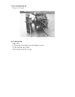
WHEN INSTALLING:
1.The mark “EX” on the cam shaft holder is the exhaust rocker arm, one-way stopper.
Install the exhaust rocker arm, the inlet rocker arm, and the rocket arm shaft.
2.Turn the flywheel to make the T mark pin correctly. The hole on the cam chain gear
should point upwards. Both the left and right concave points and the cylinder head are at
parallel position (convex part of cam shaft points upwards), then install the cam shaft on
the cylinder head.
3.Install the cam chain onto the cam shaft gear.
4.Install the locking pin.
5.Install the camshaft holder, washer and nuts on the cylinder head.
6.Lock tightly the cylinder head nuts.
Locking torque: Cam shaft holder nuts:2.0kg-m
7.Adjust the valves clearance.
Limit of Use:
IN :replace it below 25.90(125CC), 26.23mm(150CC)
EX :replace it below 25.90(125CC), 26.13mm(150CC)
NOTICE:
Do check if there is any damage on the cam rocker arm
Sliding surface.
Limit of use : replace it above 10.10mm.
Limit of use : replace it above 10.10mm.
Limit of use : replace it below 9.91mm.
Limit of use : replace it above 0.10mm.
NOTICE:
a.The tangen angle of the heat side of intake valve’s rocker arm shaft is to match
with the bolt of the cam holder.
b.The tangent angle of the exhaust valve’s rocker arm shaft is to match with the bolt
of the cam holder.
NOTICE:
a.Put some grease on the bolt thread of cam shaft holder
b.Lock the nuts of the cam shaft bracket in “cross” sequence for 2-3 times.
Summary of Contents for ALLORO 125
Page 1: ...Manufactured by Motive Power Industry Co Ltd ...
Page 17: ...C Chassis appearance 1 Apply oil 1 2 2 Apply grease 3 4 5 6 7 8 1 2 3 4 5 6 7 8 ...
Page 18: ...D Wheel bearing Final transmission mechanism gear oil Speedometer gear clean grease ...
Page 62: ...7 Remove the start idle gear fixing plate 8 Take off the idle gear ...
Page 82: ... 7 Crankcase Crankshaft A Disassembling diagram ...
Page 94: ... 1 Lubrication System ...
Page 118: ... 7 A C Generator A Dismantling AC generator B Installing AC generator ...
Page 132: ......
Page 164: ... 3 Recharge system A Recharge system diagram for M2 50 ...
Page 165: ...B Recharge system diagram for M2 125 150 ...
Page 170: ...46 Wiring diagram for M2 50 ...
Page 171: ...47 Wiring diagram for M2 125 150 ...
Page 172: ...48 Wiring diagram for M2 150 4V ...
Page 173: ...49 Wiring diagram for M2 200 ...
Page 174: ......
Page 175: ......
Page 176: ...50 Wiring diagram for M2 250 ...
Page 192: ...1 6 3 Electric system Carburetor model electric General maintenance Engine Management System ...
Page 201: ...10 G MAX 200 220 Specified engine oil synthetic 1000ml ...
Page 210: ...19 Ignition coil Dismantle the right lower cover You can see the ignition coil clearly ...
Page 215: ...1 6 5 Engine Management System EMS ...
Page 216: ...2 EMS index PGO 2nd stage EMS structure EMS units EMS diagnostic ...
Page 217: ...3 Feature of PGO 2nd stage EMS feature 1 small light 2 integrity 3 accuracy 4 simple ...
Page 220: ...6 EMS units ...
Page 221: ...7 噴油嘴 Throttle position sensor Intake pressure sensor injector Idle Speed Controller ...
Page 223: ...9 ECU Electronic Control Unit Topple snsor Second air solenoid ...
Page 224: ...10 Important PIN no of ECU ECU PIN 1 PIN 18 PIN 19 PIN 36 PIN ...
Page 235: ...21 Oxygen sensor W heater 12V 2 couple 8Ω Gr ground B output ...
Page 240: ...26 Fuel pump R B output 12V B ground R B B voltage 12V resistance 1KΩ ...
Page 243: ...29 ISC Idle Speed Control W ISC A R B ISC B G ISC B Gr ISC A ISC unit R A A 80Ω B B 80Ω ...
Page 248: ...34 EMS fuses 7 5A 10A 5A 1A 10A 15A ...
Page 250: ...36 6 6 EMS diagnostic ...
Page 251: ...37 part no S320840G01 name quick diagnostic Quick diagnostic ...
Page 254: ...40 part number S320891G01 name software adapter PC diagnostic software adapter ...
Page 255: ...41 part number S320838G01 name connect cable PC diagnostic ...
Page 258: ...44 6 7 EMS system Repairing tool ...
Page 259: ...45 pocket tester wiring pocket tester wiring part no S905310005 ...
Page 260: ...46 Ignition gauge connect minimum distance 6mm Plug cap ground ...
Page 261: ...47 Fuel pressure gauge fuel pressure gauge part no S905330008 ...
Page 263: ...49 6 8 General Electric units ...
Page 265: ...51 Signal flasher relay LED within the leg shield cover dismantle the leg shield cover first ...
Page 266: ...52 regulator within the right body cover dismantle 1 luggage comp 2 rear rack 3 body cover ...
Page 267: ...53 Fuel gauge below the middle cover dismantle 1 middle cover ...
Page 268: ...54 Measure the fuel gauge gray output black ground gray black F 4 10Ω E 80 90Ω ...
Page 275: ......


