background image

3

1. Safety Instructions 

Read and follow all instructions in this manual.

Inform yourself regarding:
– Hazards which can be caused by the pumping station;
– Hazards which can be caused by your system;
– Hazards which can be caused by the medium being 

pumped.

Avoid exposing any part of the body to vacuum.

Observe the safety and accident prevention regulations.

Regularly check that all accident prevention measures are 
being complied with.

Do not operate the turbo pumping station with open high 
vacuum flange.

Use at least 4 bracket screws to connect the high vacuum 
flange (ISO flange).

Do not disconnect the plug between the TC 600 and 
accessory components during operations.

During operations temperatures of up to 65 °C can arise in 
the lower part of the turbopump. Take care to avoid burns!

Keep leads and cables well away from hot surfaces 
(>70 °C).

The unit has been accredited protection class IP 30. When 
the unit is operated in environments which require other 
protection classes, the necessary measures must be
taken.

Do not carry out any unauthorised conversions or 
alterations to the turbo pumping station.

When returning individual components please observe the 
shipping instructions (refer to the operating instructions 
for the pumping station components).

Modifications reserved.

1.1. For Your Orientation

In the text

Working instruction: here, you have to do something.

Symbols used

The following symbols are used throughout in illustrations.

High vacuum flange

Fore-vacuum flange

Air cooling

Sealing gas connection

Venting connection

Electric connection

Abbreviations used

DCU = Display and Operating unit

TC = Electronic drive unit, turbopump

TPS = Power unit

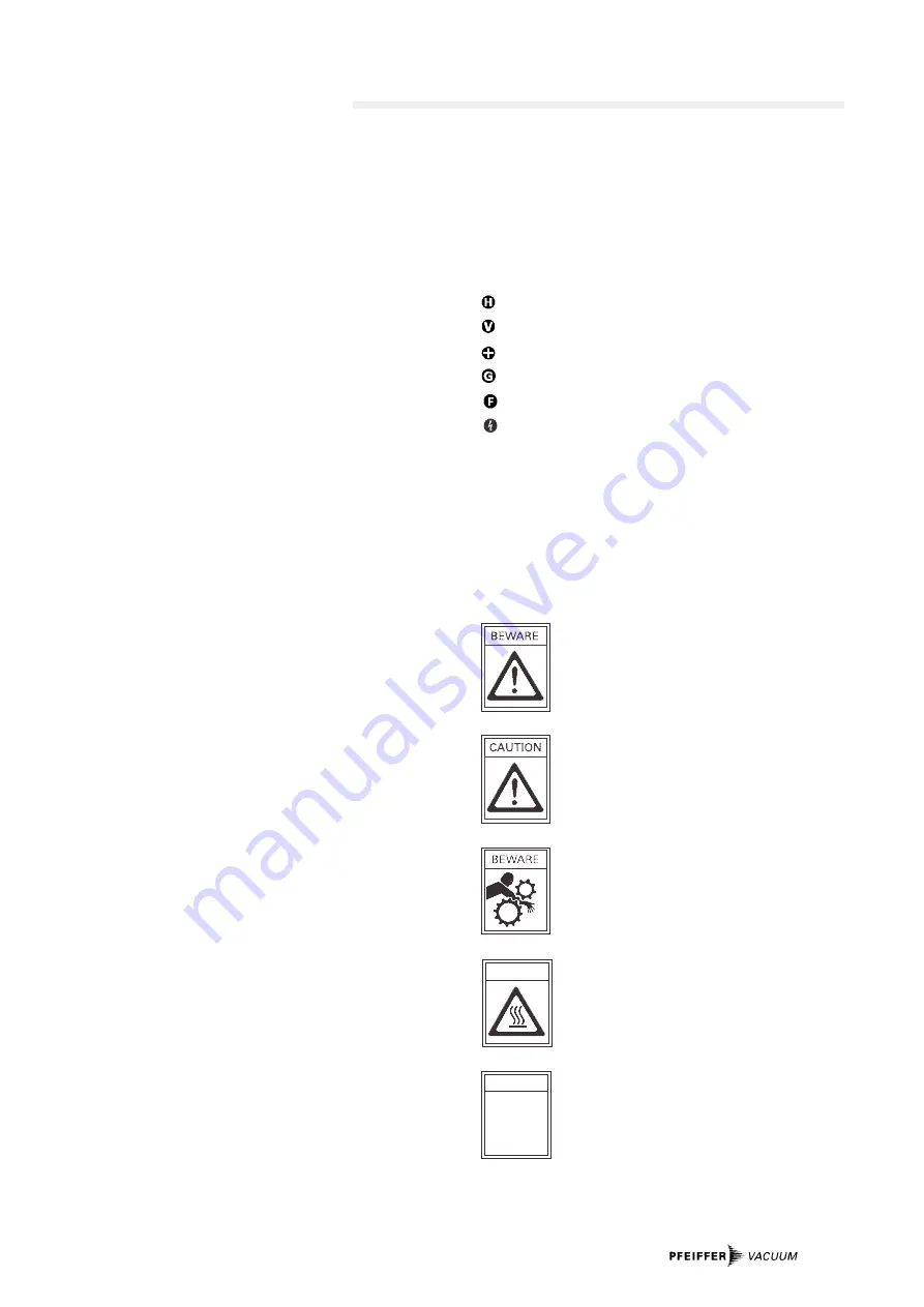
1.2. Pictogram Definitions

Danger of personal injury.

Danger of damage to the pumping station or to
the system.

Danger of injury from rotating parts.

Danger of burns from touching hot parts.

Attention to particulary important information
on the product, handling the product or to a
particular part of the documentation.

PLEASE NOTE

BEWARE

Summary of Contents for TSH 071 E

Page 1: ...Operating Instructions Turbomolecular Drag Pumping Stations Economy Version TSH 071 E TSU 071 E PT 0067 BE A 0105...

Page 2: ...6 3 5 Connecting The Vacuum System 6 3 6 Cooling 6 3 7 Connecting The Casing Heating 6 3 8 Connections Diagram 7 4 Operations 8 4 1 Lubricant Filling 8 4 2 Before Starting 8 4 3 Starting 8 4 4 Switchi...

Page 3: ...hen the unit is operated in environments which require other protection classes the necessary measures must be taken Do not carry out any unauthorised conversions or alterations to the turbo pumping s...

Page 4: ...the Display And Operating Unit DCU OO1 The Display And Operating Unit DCU OO1 serves to control and monitor the pumping station The DCU can be detached from the pumping station and ope rated with the...

Page 5: ...umps is fitted and filled ready for operation Permissible magnetic field 4 mT Set up the pumping station on a horizontal surface In order to avoid the build up of heat when operating the pumping stati...

Page 6: ...ng is switched off As far as possible thermally insulate the heating sleeve and pump casing during installation When heating do not touch the pump casing and heating sleeve The relay box of the casing...

Page 7: ...release Motor turbopump Pumping station Heating Reset Standby PWM ON touch relation 25 75 Switching output 1 24 VDC max 50 mA Switching output 2 24 VDC max 50 mA GND Relay box Heating Mains input heat...

Page 8: ...or is abnormally high the valve can be opened when the pumping station is running Once the final pressure has stabilized the valve can be closed again HINWEIS 1 2 8 7 6 3 4 5 Display And Operating Un...

Page 9: ...levant operating instructions see Section 2 3 6 1 Lubricant The bearing on the diaphragm vacuum pump is lubricated for the duration of its working life The lubricant reservoir on the turbopump should...

Page 10: ...th the Code of Federal Regulations CFR 49 Part 173 240 Definition and Preparation We will carry out the decontamination and invoice this work to you if you have not attached this note This also applie...

Page 11: ...11 8 1 Dimensions 300 338 150 100 300 Threaded holes 4xM4 for securing the heating relay box...

Page 12: ...M 041 902 T PM 800 542 BN Water cooling PM 016 000 T PM 800 546 BN Sealing gas Valve PM Z01 142 Protective grill DN 63 PM 006 597 R Splinter shield DN 40 PM 006 375 X DN 63 PM 006 376 X Pressure Gauge...

Page 13: ...The repair and or service of vacuum components will only be carried out if a correctly completed declaration has been submitted Non completion will result in delay The manufacturer could refuse to acc...

Page 14: ...e product specified below is in accordance with the provision of EU Machinery Directive 98 37 EEC Annex II A EU Electromagentic Compatibility Directive 89 336 EEC and EU Low Voltage Directive 73 23 EE...

Page 15: ...l Bldg 690 Sukhumvit Road Klongton Klongtoey Bangkok 10110 telephone 662 259 6244 telefax 662 259 6243 U S A Pfeiffer Vacuum Inc 24 Trafalgar Square Nashua NH 03063 1988 USA telephone 1 603 578 6500 t...

Reviews: