11
Installation
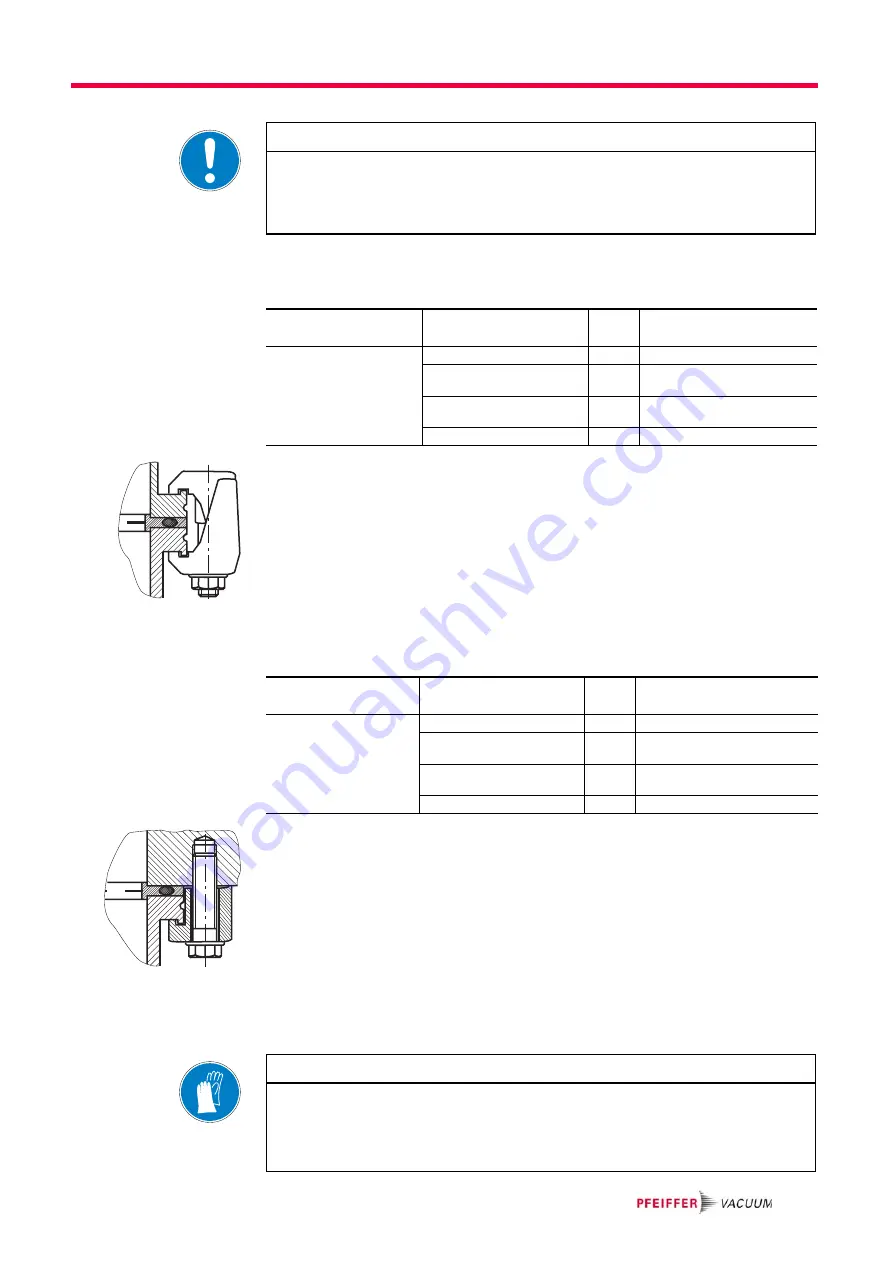
Installation of ISO-K
flange with ISO-K
flange
For the installation of the flange connections the following components are avail-
able:
Î
Mind that the sealing surfaces are not damaged.
Î
Flange the turbopump according to the drawing and together with the compo-
nent parts in the mounting material kit.
Î
Use the required number of bracket screws.
Î
Tighten the bracket screws crosswise in three steps.
Î
Tightening torque: 5, 15, 25 ±2 Nm
Installation of ISO-K
flange with ISO-F
flange
For the installation of the flange connections the following components are avail-
able:
Î
Mind that the sealing surfaces are not damaged.
Î
Flange the turbopump according to the drawing and together with the compo-
nent parts in the mounting material kit.
Î
Use 8 claw grips.
Î
Tighten the claw grips crosswise in three steps.
Î
Tightening torque: 3, 10, 16 ±1 Nm.
Installation of CF-
flanges
NOTE
Possible damage to the pump
If a pump with an ISO-K flange is fastened to a vacuum chamber with an ISO-F flange
or if ISO-KF flanges are used, sudden blocking of the rotor can result in twisting
despite proper installation.
Connection nominal
diameter
Designation
Pieces Ordering No.
DN 100 ISO-K
Centering ring (coated)
1
PM 016 210-U
Centering ring (coated) with
splinter shield
1
PM 016 211-U
Centering ring (coated) with
protective screen
1
PM 016 212-U
Bracket screw
6
PF 300 110-T
Connection nominal
diameter
Designation
Pieces Ordering No.
DN 100 ISO-K
DN 100 ISO-F
Centering ring (coated)
1
PM 016 210-U
Centering ring (coated) with
splinter shield
1
PM 016 211-U
Centering ring (coated) with
protective screen
1
PM 016 212-U
Claw grip
8
PF 301 100-T
NOTE
Preservation of sealing capacity
Observe the following to preserve sealing capacity:
Î
Touch seals only with gloves.
Î
Make sure sealing lips are undamaged.


