background image

Malfunctions

37

9

Malfunctions

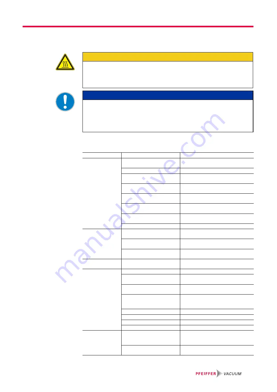
Please note the following instructions should the pump malfunction:

9.1

Rectifying malfunctions

CAUTION

Hot surface!

Danger of burns if hot parts are touched. The surface temperature of the pump may rise 
above 105 °C in case of malfunction.

Carry out work on the pump only after it has cooled to a safe temperature.

NOTICE

Motor overload!

Depending on the malfunction (e.g. blocking during cold start), the motor may not be 
sufficiently protected by the built-in thermal protection switch from damage through 
overheating.

Implement an additional network safety device.

Problem

Possible causes

Remedy

Pump will not start up No mains voltage or voltage does 

not correspond to the motor data

Check mains voltage and mains fuse protec-
tion; check motor switch

Ambient temperature too low

Warm up pump to > 12 °C

Suction chamber not flooded

Flood on suction side after switching off 
pump

Thermal cut-off switch has re-
sponded

Detect and fix cause of overheating; allow 
pump to cool off if necessary.

Defective motor cut-off switch 
(building side)

Re-set or replace switch.

Dirty pump system

Clean pump; notify Pfeiffer Vacuum service 
department, if necessary.

Damaged pump system

Clean and overhaul pump; notify Pfeiffer 
Vacuum service department, if necessary.

Motor defective

Replace motor

Pump switches off af-
ter a while after being 
started

Thermal protection switch of the 
motor has responded

Detect and fix cause of overheating; allow 
pump to cool off if necessary.

Mains fuse protection triggered 
due to overload (e.g. cold start)

Warm up pump

Exhaust pressure too high

Check opening of exhaust line and exhaust 
accessories

High increase in oper-
ating temperature

Fault in cooling water circuit

Check flow paths for dirt and lime deposits; 
clean, if necessary.

Pump not achieving 
the ultimate pressure

Leak in the system

Fix leak

Falsified measuring result

Check gauge, test ultimate pressure without 
connected system.

Pump or connected accessories 
dirty

Clean pump and check components for dirt.

Dirt in operating fluids

Operate pump for a longer period of time 
with opened gas ballast valve or replace op-
erating fluids

Gas ballast valve is open

Close valve.

Silencer is open

Set/adjust the silencer

Operating fluids fill level too low

Fill up operating fluids

Pump is damaged

Contact Pfeiffer Vacuum Service.

Pumping speed of 
pump too low

Intake line not well-dimensioned

Keep connections as short as possible and 
see that cross-sections are sufficiently di-
mensioned

Exhaust pressure too high

Check opening of exhaust line and exhaust 
accessories

Summary of Contents for BA 251

Page 1: ...PK 0156 BEN L 1607 OPERATING INSTRUCTIONS EN BA 251 501 Rotary Vane Pump ...

Page 2: ...ion or measurement connection 18 5 8 Operating fluid level monitoring option 19 5 9 Operating fluid temperature monitoring option 21 6 Operation 22 6 1 Before switching on 22 6 2 Switching on the pump 23 6 3 Pumping condensable vapours 24 6 4 Topping up the operating fluid 27 6 5 Switching off and venting 27 7 Maintenance 28 7 1 Precautions 28 7 2 Changing the operating fluid 29 7 3 Changing the k...

Page 3: ...Table of contents 3 11 2 Drawings 41 12 Accessories 43 13 Technical data and dimensions 44 13 1 General 44 13 2 Technical data 45 13 3 Dimensions 46 Declaration of conformity 49 ...

Page 4: ... The safety instructions in Pfeiffer Vacuum operating instructions are the result of risk evaluations and hazard analyses and are oriented on international certification stan dards as specified by UL CSA ANSI Z 535 SEMI S1 ISO 3864 and DIN 4844 In this document the following hazard levels and information are considered DANGER Imminent danger Indicates an imminent hazardous situation that will resu...

Page 5: ...allast valve Power connection Prohibition of an action to avoid any risk of accidents the disregarding of which may result in serious accidents Warning of a displayed source of danger in connection with operation of the unit or equipment Command to perform an action or task associated with a source of dan ger the disregarding of which may result in serious accidents Important information about the...

Page 6: ...ed to make operating personnel aware of dangers originating from the vacuum pump the pumped medium and the entire system Installation and operation of accessories Pfeiffer Vacuum pumps can be equipped with a series of adapted accessories The in stallation operation and maintenance of connected devices are described in detail in the operating instructions of the individual components For informatio...

Page 7: ...taining impurities such as particles dusts and condensate note the vapour compatibility levels of the pump pumping of substances that tend to sublime use of the vacuum pump to generate pressure pumping of liquids the use of operating fluids not specified by Pfeiffer Vacuum connection to pumps or units which are not suitable for this purpose according to their operating instructions connection to u...

Page 8: ...ge Check that all the openings on the pump are securely closed Fill up the pump with new operating fluid to the top edge of the sight glass Store the pump only dry and dust free indoors within the specified environmental con ditions In rooms with moist or aggressive atmospheres the pump must be airproof shrink wrapped in a plastic bag together with a bag of desiccant After storage periods longer t...

Page 9: ...number Serial number Type and amount of operating fluid Date of manufacture For motor specific data please see the separately installed motor rating plate Scope of delivery Pump with without motor Operating fluid P3 for standard pump Centering ring with O ring Flange cover for vacuum and exhaust flange Operating instructions Pump types Pump type Pump designs BA 251 Pump on without base frame BA 50...

Page 10: ...tes contingent on the pump temperature the cooling water flow level so that the pump operating temperature is maintained Fig 2 Rotary Vane Pump BA 251 BA 501 Range of application Being of a robust design the pumps are especially suitable for vacuum generation in in dustrial applications The pumps can be used as stand alone units or as the pre stage to roots pumps 1 Operating fluid collecting vesse...

Page 11: ...d the respective O ring in the intake port Clear welded lines of any welding scales loose parts etc before installation The connection between the pump and the vacuum chamber should be kept as short as possible Depending on the pump type use metallic hoses or PVC hoses with flange con nections Separators filters etc may be installed upstream to protect the pump see acces sories However please obse...

Page 12: ...it optional The cooling water connection unit includes the following components and is mounted as shown in Fig 3 Shut off valve Dirt trap Pressure monitor and Fastening clip Installing pressure monitor option The pressure monitor can be used as an effective means of monitoring the pump against cooling water failure WARNING Emission of toxic substances from the exhaust Danger of poisoning from emit...

Page 13: ...sure as overpressure based on atmospheric pressure Fig 4 Set pressure monitor 3 Set switch point ph at 2 bar contact 1 4 closes at cooling water pressure of 2 bar Set switch point pl at 1 bar if the pressure drops to 1 bar contact 1 2 closes and contact 1 4 opens 2 Shut off valve 3 Pressure monitor 3 1 Reducing nipple G 3 8 1 2 3 2 Dirt trap G 1 2 3 3 Nipple G 1 2 3 4 Tee G 1 2 41 Cooling water co...

Page 14: ...current which flows in the supply lines Fig 5 Motor coil and connecting plate of Delta Connection for low voltage Star Connection The ends of the three coils are connected at the star center The terminal voltage is the cube root of the coil voltage the mains and the coil current are the same Star connec tions are denoted by the symbol Y DANGER Voltage bearing elements Danger to life from electric ...

Page 15: ...ction against overload Other ap proved motor temperature monitoring can be used also by the operator Tripping devices store the shutdown event and need to be manually switched back on again via the integrated RESET button or via the external RESET S3 Mains ON is de tected as an automatic RESET Set up the connections so that the directional rotation indicated on the pump is main tained regardless o...

Page 16: ...p run up time max 30 s the shutdown can occur directly Electrical connection with cooling water pressure monitor Prepare the circuitry of the motor with cooling water pressure monitor 3 according to the circuit diagram A combination with a PTC resistor temperature sensor 3TF is also pos sible US Control voltage S1 OFF button S2 ON button S3 RESET button external K1 Contactor F1 F4 Fuses T1 T3 PTC ...

Page 17: ...Installation 17 Fig 8 Connection with cooling water pressure monitor 3 Pressure monitor F3 Motor protection switch PE L1 L2 L3 N PE 3 ...

Page 18: ... bearing oil chambers are factory filled with P3 lubricant Prior to commissioning check fill level of both oiler 39 The oiler should always be filled to a max of one third when the pump is cold top up as required 5 7 Setting up ventilation or measurement connection The ventilation or measurement connection complies with DN 10 ISO KF and for serial production pumps is sealed vacuum tight with a bla...

Page 19: ...rmissible level The level switch is preset ex works Fig 10 Operating fluid level monitoring Turn off the vacuum pump vent to atmospheric pressure and allow to cool Drain off operating fluid partially Loosen locking screw 83 and screw it out Install extension 83 1 between the pump dome and the level switch 83 2 as a protec tion against excessively high temperatures 50 6 Pump dom 83 Locking screw 83...

Page 20: ... fluid level monitoring The pump has to be running Create reproducible operating conditions e g measure ultimate pressure or intake pressure 500 hPa if the intake pressure cannot be measured then for example allow for a time de lay of 10 min between the reaction and the alarm Disable the alarm signal during the warm up phase or in the case of high process dependant gas throughput if necessary ...

Page 21: ... fluid temperatur Fig 11 Install the temperature sensor Turn off the vacuum pump vent to atmospheric pressure and allow to cool Drain off operating fluid partially Unscrew locking screw 34 G 1 2 Screw in resistance thermometer 34 1 take care with O ring Parameter Resistance thermometer Protection category IP 65 Method of measurement PT 100 Temperature range 50 400 C 34 1 34 6 ...

Page 22: ...efore or at the same time as the pump is started Protect the pump sufficiently from taking in contaminants by means of suitable precau tions e g dust filters if necessary check operating fluid regularly or replace at short er intervals Open cooling water supply lever down screw 123 at the cooling water controller 41 by using a screw driver and vent the cooling chambers Switch on pump only with ven...

Page 23: ...agent The thermal sensor is submerged in the operating fluid and connected via a capillary tube to the bellows in the valve head The cooling water controller 41 is factory set If other temperatures are required the pump temperature can be changed by turning setting disk 1 The respective settings as well as the maximum temperature must only be made after consulting with Pfeiffer Vacuum NOTICE V bel...

Page 24: ... or inert gas option is fed into the working chamber at the beginning of the compression phase via the gas ballast valve 5 1 Setting disk 2 Setting scale 3 Arrow for temperature setting 41 cooling water controller 123 Vent screw F C Q 3 2 1 123 41 NOTICE Bad final vacuum and damage to the pump Danger of condensation and corrosion due to exceeding the water vapour compatibility during operation wit...

Page 25: ...rator and or a solenoid valve to small flange connection KF 10 Fig 14 Conversion set for gas ballast valve with solenoid valve and or dust separator Dust separator A dust separator should be used if dust laden air is sucked in It should be noted that when the dust separator becomes fouled the amount of gas ballast fed de creases and the risk of condensation from process media increases Solenoid va...

Page 26: ...e Select the type and amount of flushing gas depending on the process consult Pfei ffer Vacuum if necessary NOTICE Flushing gas pressure higher than allowed endangers the operational reliability of the pump The power input of the pump the temperature and the ejection of operating fluid will in crease Observe the maximum permissible flushing gas pressure of 1500 hPa absolute Set the amount of flush...

Page 27: ... purpose the valve s control can be coupled with the motor voltage Open magnetic venting valve at measurement connection 50 and vent the pump To prevent premature venting the venting valve can be coupled with the shut off valve s position indicator If the ambient temperature is less than 0 C the cooling water must be drained at Pos 62 after the pump is switched off and after prolonged down time se...

Page 28: ... their use must be observed Use only alcohol or similar agents for cleaning pump parts WARNING Danger of injury from moving parts After power failure or motor shutdown due to overheating the motor may restart auto matically Secure the motor so that it cannot be switched on while any work is being performed on the pump If necessary dismantle the pump from the installation for inspection WARNING Pum...

Page 29: ... example can be read off the colour scale in accordance with DIN 51578 request the supplementary sheet PK 0219 BN or download it from the Internet Fill the specimen in a test tube or some similar vessel and test by holding against the light Where discolouration is dark yellow to red brown equivalent to 4 5 on the scale change operating fluid Turn off the vacuum pump vent to atmospheric pressure an...

Page 30: ...again if necessary Screw the operating fluid drain screw 90 back in Fill up with operating fluid and check the filling level see p 18 chap 5 6 90 WARNING Hot operating fluid Danger of burns when draining due to contact with skin Wear suitable protective clothing Use a suitable collecting vessel WARNING Operating fluid may contain toxic substances from the pumped media Danger of poisoning from the ...

Page 31: ... their filter elements pay attention to whether more operating fluid is required Fill the pump for the final time with the third filling Note down the current type of operating fluid in an appropriate place on the pump preferably on the type plate NOTICE Changing the type of operating fluid A change of operating fluid type can be only be made between mineral P3 and syn thetic operating fluid D1 It...

Page 32: ...g chambers Cleaning the dirt trap Fig 17 Cleaning the dirt trap Stop cooling water supply Open sealing plug on dirt trap 3 2 pay attention to seal Clean sieve insert 7 5 Checking the V belt drive The correct belt bias is crucial to efficient power transmission and achieving the usual belt lifespans The belts will fail prematurely if the bias is too low or too high Excessive belt bias frequently re...

Page 33: ...g balance with load hook A in centre of strand Apply required test load f of 50 N according to scale C pull spring balance at right angle to the strand If necessary correct the bias until the setpoint value is reached Observe the drive during the first few hours of operation and retension after approx 0 5 to 4 hours running time under full load Check the belt bias again after approx 24 hours of op...

Page 34: ...nsert 114 and remove circlip 113 Pull valve insert 114 from valve housing 104 Undo screws 116 and remove valve springs 115 Clean all parts and examine for wear Replace gasket 110 if necessary Reassemble in the reverse sequence 100 Needle valve 101 Locking nut 102 Self locking nut 103 Valve nut 104 Valve housing 105 Intermediate piece 106 Clamping block 107 Washer 108 Washer 109 Valve plate 110 Gas...

Page 35: ...using a standard screwdriver when the pump is running at operating temperature and vacuum flange and gas ballast valve are closed Close needle valve 100 111 and wait until you hear oil hammer Untwist needle 100 111 until the oil hammer noise disappears approx 1 2 rotation Hold needle valve 100 111 in position with the screwdriver and tighten fixing nut 101 If the silencer is set correctly the pump...

Page 36: ...ng fluid before using the pump Do not store pump in the vicinity of machines lanes etc because strong vibrations can damage the rotor bearings 8 2 Re starting Visually inspect the inner of the pump dome before taking it into operation If there is ev idence of rust on the parts of the pump which form the housing then do not take it into operation and contact Pfeiffer Vacuum Service Depending on how...

Page 37: ...ump system Clean and overhaul pump notify Pfeiffer Vacuum service department if necessary Motor defective Replace motor Pump switches off af ter a while after being started Thermal protection switch of the motor has responded Detect and fix cause of overheating allow pump to cool off if necessary Mains fuse protection triggered due to overload e g cold start Warm up pump Exhaust pressure too high ...

Page 38: ...rt in silencer Clean or replace the silencer Damage in pump system Clean and overhaul pump notify Pfeiffer Vacuum service department if necessary Motor bearing defective Replace motor notify Pfeiffer Vacuum ser vice department if necessary Problem Possible causes Remedy NOTICE Service work should be carried out by a qualified person only Pfeiffer Vacuum is not liable for any damage to the pump res...

Page 39: ...it in the shipment required Dismantle all accessories Drain operating fluid lubricant Drain cooling medium if used Send the pump or unit in its original packaging if possible Sending of contaminated pumps or devices No units will be accepted if they are contaminated with micro biological explosive or ra dioactive substances Hazardous substances are substances and compounds in ac cordance with the ...

Page 40: ...s of the discharge valves Also the O ring of the pump dome is included Cooling water controller Cooling water controller Sleeve of the thermal sensor Parts of the piping 11 1 Spare parts packages The spare parts packages listed here are only applicable for standard models Please state all information on the rating plate when ordering spare parts Other spare parts than those described in this manua...

Page 41: ...Spare parts 41 11 2 Drawings ...

Page 42: ... Locking screw with sealing ring 35 Vane spring 36 Strainer 37 Guide pin only for BA 501 38 Cylinder roller bearing 39 Oiler 40 Sight glass 41 Cooling water controller 42 Double nipple 44 Screwed connection 45 Angle 46 Seal 47 Radial shaft seal 48 Radial shaft seal 49 O ring 51 O ring 52 O ring 54 O ring 55 O ring 56 O ring 57 O ring 57 O ring 58 O ring 59 O ring 60 O ring 61 O ring 63 Screw 64 Sc...

Page 43: ...gas ballast valve to KF connection PK 133 863 T SAS 63 dust separator DN 63 ISO K polyester filter PK Z60 511 Magnetic gas ballast valve 230 V 50 60 Hz PK V52 001 Designation BA 501 KAS 100 condensate separator PK Z10 012 OME 160 M oil mist filter for pumping speeds of up to 500 m3 h PK Z40 014 Oil return unit ORF 005 standard version PK Z90 065 FAK 100 activated carbon filter PK Z30 012 PTC resis...

Page 44: ...ble gas throughput units mbar bar Pa hPa kPa Torr mm Hg mbar 1 1 10 3 100 1 0 1 0 75 bar 1000 1 1 105 1000 100 750 Pa 0 01 1 10 5 1 0 01 1 10 3 7 5 10 3 hPa 1 1 10 3 100 1 0 1 0 75 kPa 10 0 01 1000 10 1 7 5 Torr mm Hg 1 33 1 33 10 3 133 32 1 33 0 133 1 1 Pa 1 N m2 mbar l s Pa m3 s sccm Torr l s atm cm3 s mbar l s 1 0 1 59 2 0 75 0 987 Pa m3 s 10 1 592 7 5 9 87 sccm 1 69 10 2 1 69 10 3 1 1 27 10 2 ...

Page 45: ...z 490 min 1 345 min 1 Nominal rotation speed pump 60 Hz 490 min 1 345 min 1 Emission sound pressure level without gas bal last at 50 Hz 63 dB A 65 dB A Emission sound pressure level without gas bal last at 60 Hz 63 dB A 65 dB A Ambient temperature 12 40 C 12 40 C Protection category IP 55 IP 55 Rated power 50 Hz 11 kW 15 kW Rated power 60 Hz 13 kW 18 kW Mains requirement voltage 50 Hz 230 400 5 V ...

Page 46: ...46 Technical data and dimensions 13 3 Dimensions Fig 20 BA 251 1030 1528 746 840 884 277 522 220 520 130 734 480 ø18 6x 980 DN 63 ISO F DN 10 KF DN 63 ISO K 467 25 ...

Page 47: ...Technical data and dimensions 47 Fig 21 BA 501 160 891 1130 990 200 1070 100 645 685 1907 1260 715 310 ø18 6x 442 1204 672 DN 100 ISO K DN 100 ISO F DN 10 KF 280 28 ...

Page 48: ...48 Technical data and dimensions Frame with vibration isolators A A 1 5 A A 1150 5 1113 5 137 217 237 694 5 Ø 2 2 4 x 488 1374 5 1337 5 851 5 645 BA 251 BA 501 ...

Page 49: ...he technical documentation is Mr Sebastian Ober beck Pfeiffer Vacuum GmbH Berliner Straße 43 35614 Aßlar UnoLine Plus BA 251 501 Harmonised standards and national standards and specifications which have been ap plied DIN EN ISO 12100 2010 ISO 21360 1 2 2012 DIN EN 61000 6 3 2007 DIN EN 1012 2 2011 12 DIN EN 61000 6 1 2007 DIN EN 61000 6 4 2007 DIN EN ISO 13857 2008 DIN EN 61000 6 2 2006 DIN EN ISO...

Page 50: ...e are the only supplier of vacuum technology that provides a complete product portfolio COMPETENCE IN THEORY AND PRACTICE Benefit from our know how and our portfolio of training opportunities We support you with your plant layout and provide first class on site service worldwide Are you looking for a perfect vacuum solution Please contact us Pfeiffer Vacuum GmbH Headquarters Germany T 49 6441 802 ...

Reviews: