11 - 18
Adjustment
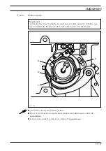
Fig. 11 - 16
6
3
2
1
5
6
0,3 mm
4
4
11
.05.05
Release trip
Requirement
In needle rise position and with control lever
4
engaged, there must be a clearance of
approx.
0.3 mm
between the bolt of the control lever and the base of the cam track.
●
Bring the machine to needle rise position.
●
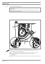
Manually activate engaging lever 1 so that pawl
2
engages.
●
Taking care to ensure that screw
3
is still loose, press control lever
4
down to the base
of the track of control cam
5
.
●
Maintaining this position, lightly tighten screw
3
while bringing release trip
6
into a
resting position against engaging lever
1
and laterally against control lever
2
in the
direction of the arrow.
●
By lightly tapping on release trip
6
in the direction of the arrow, while simultaneously
tapping control lever
4
, create a distance between the pin and the base of the cam track
which corresponds with the
requirement.
●
In this position tighten screw
3.


