2
3
2
3
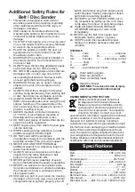
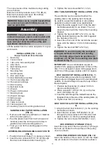
3. Tighten the two screws M4*0.7-12 (2).
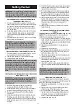
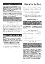
Disc table asseMbly installation (fig.
6)
The worktable can be used with either the
sanding disc or the sanding belt. It should
be used to support workpieces in all sanding
operations except inside curve applications.
1. Insert the table support rod (1) into the disc/
belt table assembly (3) as shown. The rod
should be flush with the front of the mounting
bracket.
2. Tighten the hex bolt M8*1.25-12 (4) on the
table bracket making sure the bolt is against
the flat side of the rod.
3. Insert the other end of the rod into the sander
base until the table is 1.59 mm from sanding
disc.
4. Tighten the hex bolt M8*1.25-70 (2).
iMPortant:
Use a combination square to
position mitre gauge perpendicular to face of the
disc. If it is not square loosen mitre gauge knob
and move mitre gauge, slightly, until it is square.
belt backstoP installation (fig. 7)
The belt backstop prevents the workpiece from
being pulled or dragged beyond the sanding belt
surface. It should always be used to help control
the workpiece.
1. Position belt backstop (1) about 1.59 mm
above sanding table (2).
2. Place a washer 1/4*3/4-1/16 (3) on the hex
bolt 1/4*20UNC-1/2 (4).
3. Insert the bolt through the slotted hole into the
threaded hole in the side of the sanding table (2).
4. Tighten hex bolt (4) securely.
belt DUst collector installation (fig.
8)
1. Attach the belt dust collector (1) to the sanding
belt table as shown.
2. Insert the two screws 10#*24UNC-1/4 (2)
through the two washers 3/16*3/8-0.02, belt
dust collector (1) into the sanding belt table.
3. Tighten the two screws 10#*24UNC-1/4 (2).
hex wrench storage (fig. 9)
Insert the long end of the hex wrench (1) through
the hole (2) located on the surface of the pulley
cover as shown.
oPen enD wrench storage (fig. 10)
Insert the handle of the wrench (1) into the metal
clip (2) located on the back of sander as shown.
The noise levels of this machine during cutting
are as follows:
Maximum sound pressure level:
75.6 dB (A)
Maximum sound power level: 88.6 dB (A)
Uncertainties equal to 3 dB.
Lift the sander from the carton and place it on your
work bench.
installation (fig. 1, 2, 3)
know your belt / Disc sander
1. Back stop
2. Tension lever
3. 100 x 914 mm sanding belt
4. Idler drum
5. Belt tracking knob
6. Table stop
7. Mounting hole
8. On/Off switch
9. Disc dust chute
10. Disc/Belt table assembly
11. 152 mm sanding disc
12. Hex wrench storage
13. Disc housing
14. Belt dust chute
15. Wrench
16. Power cord bracket
17. Mounting hole
18. Wrench storage
19. Mitre gauge
20. Bevel scale
21. Table lock knob
22. Table support rod
23. Auxiliary hole for mounting table to belt
sanDing Disc PaPer installation
(fig. 4)
1. Remove and clean any adhesive or material
left on the disc plate (1).
2. Peel the plastic back from Velcro base and
carefully press the velcro pad (2) firmly in
position around the sanding plate (1).
3. Then you can fix the sanding paper on the
velcro pad.
asseMbling Disc sanDing DUst chUte
(fig. 5)
1. Position disc dust chute (1) in place as shown.
2. Insert the two screws M4*0.7-12 (2) through
the disc dust chute and disc housing (3).
warning! to avoid trapping the workpiece
or fingers between the table and sanding
disc, the table edge should be positioned a
maximum of 1.59 mm from sanding disc plate
as shown in fig. 6.
warning! noise can be a health hazard. when
the noise level exceeds 80 db(a), be sure to
wear ear protection.
assembly
warning! for your own safety, never
connect the plug to power source outlet until
all assembly steps are completed and you
have read and understood the safety and
operational instructions.
Summary of Contents for ENERGYSand-100
Page 8: ...8 8 ...
Page 24: ...24 24 Sommaire GB P 1 7 D P 9 15 F P 17 23 The original instruction manual is in English ...
Page 29: ...29 29 Fig 27 Fig 25 Fig 26 4 3 9 4 8 7 6 5 2 3 1 2 1 Fig 28 Fig 29 ...
Page 30: ...GB Combiné ponceur bandes et disque ENERGYSand 100 MANUEL D UTILISATION ...


