background image

15

Operation & Installation Manual

Signature  Series Beer Dispensers (HP15, HP24 and HP48 models)

DOOR OPTIONS

Perlick  residential  units  offer  a  variety  of  door  panel  design 
alternatives;  solid  stainless  steel,  solid  wood  overlay,  glass  with 
stainless steel trim and glass with wood overlay trim.

Solid stainless steel and stainless steel glass doors are shipped from 
the  factory  with  decorative  stainless  steel  panels  and  handles  in 
place on the appliance.

Solid wood overlay and glass wood overlay doors are designed to 
accept  a  decorative  front  panel  to  match  surrounding  cabinetry 
and door handles. The panel and door handles are supplied by the 
customer.

All Perlick units accept any of the above door configurations and 
are fully interchangable.

I

MPORTANT NOTE:

 Units with a beer dispenser only can utilize a 

solid stainless steel door or solid wood overlay door.

I

MPORTANT NOTE:

 Glass with stainless trim and glass with wood 

trim may sweat in conditions with relative humidity over 75%.

WOOD OVERLAY INSTALLATION

Before beginning installation, check all components for proper fit 
and finish.

WARNING

•  All overlay doors require a trim panel of at least 3/4” thick.

•  The solid wood overlay panel should not weight more than 

20 pounds.

•  The glass wood overlay panel should not weight more than 

10 pounds.

The following instructions cover installing a solid wood overlay or 
glass wood overlay panel and handle to a door or drawer. 

IMPORTANT  NOTE:

  Contact  the  factory  or  visit  www.

bringperlickhome.com  for  full  size  wood  overlay  panel  layouts. 
Once on the site, select ‘Service and Support’ from the top menu 
bar and click on ‘Wood Overlay Templates’. Take care in chosing the 
correct template for your specific model.

I

MPORTANT  NOTE:

  You  must  install  optional  lock  and  handle 

PRIOR to mounting the wood overlay onto the door frame. 

Panel drawings:
Refer to Figure 15 for 15” solid wood overlay panel (page 16).
Refer to Figure 17 for 24” solid wood overlay panel (page 18).
Refer to Figure 18 for 24”  for glass wood overlay panel (page 19).
Refer to Figure 19 for 24” drawer wood overlay panel (page 20).

Door Lock Installation (optional)

When installing to wood overlay, perform lock installation before 
mounting wood overlay to door.

1. See Figure 14 (below), attaching mounting bracket to wood 

overlay.

2. Insert lock body and attach with nut.

Lock installation drawings:
Refer to Figure 16 for Lock Installation on 15” solid wood overlay 
panel (page 17).
Refer to Figure 20 for Lock Installation on 24” solid wood overlay 
panel (page 21).
Refer to Figure 21 for Lock Installation on 24” glass wood overlay 
panel (page 22).
Refer to Figure 22 for Lock Installation on 24” drawer wood overlay 
panel (page 23).

Mounting bracket

Screw

Lockwasher

Lock strike

Nut

Lock bracket

Lock body

Figure 14 - Lock  installation

Summary of Contents for Signature Series HP15TS

Page 1: ...Luxury Operation Installation Manual Signature Series HP15 HP24 and HP48 inch models Form No Z2259 Rev 06 07 2012 HP15TS HP24TS HP48RT Beer Dispenser Models Only ...

Page 2: ......

Page 3: ... will help you quickly identify a problem and get it remedied In the event you require assistance please contact the dealer where you purchased your unit WARRANTY REGISTRATION CARD To request information or service the model number and serial number must be provided This information is located on the inside ceiling of the unit and on the warranty registration card included with information packet ...

Page 4: ...o malfunction This could void the warranty Never install the unit behind closed doors Be sure front louvered toe plate is free of obstruction Obstructing the airflow can cause unit to malfunction and may void the warranty CAUTION Use only genuine Perlick replacement parts Imitation parts can damage the unit and may void the warranty INSTALLATION INSTRUCTIONS GENERAL All electrical instructions ass...

Page 5: ... 3 8 1 5 8 1 15 16 26 9 16 11 Power cord 6 5 8 off floor 16 7 7 8 7 16 with 24 1 16 toleramce 25 7 16 Values may change due to custom pull with a wood overlay door SCALE 1 10 DATE MILWAUKEE WI 53223 PERLICK CORPORATION NOT TO BE COPIED OR USED DETRIMENTAL TO OUR INTERESTS DR PRINTED 0 95004 slddrw 4 12 2012 95004 9 30 09 DAS PROPERTY OF THE PERLICK CORP SHEET 2 OF 3 Signature Series HP15 Models Ta...

Page 6: ...18 3 16 24 7 8 Tapping Leg levelers can add Signature Series HP24 Models when fully extended 3 4 to these dimensions Also fits two sixth barrels when shelf is removed 95005 slddrw SCALE 1 10 MILWAUKEE WI 53223 PERLICK CORPORATION NOT TO BE COPIED OR USED DETRIMENTAL TO OUR INTERESTS DR PRINTED DATE 4 12 2012 95005 9 30 09 DAS PROPERTY OF THE PERLICK CORP SHEET 2 OF 3 34 1 4 8 7 23 3 7 8 Power cord...

Page 7: ...r with 1 16 tolerance 24 25 7 16 Values may change due to custom pull with a wood overlay door Signature Series HP48 Models 34 5 16 4 47 7 8 5 1 4 19 5 8 26 9 16 19 7 8 19 7 8 24 7 8 26 9 16 20 11 16 12 3 4 26 9 16 6 3 8 11 3 4 18 1 8 19 5 8 5 1 4 12 3 4 1 1 4 Min clearance from a corner to acheive 90 door swing 24 15 16 Min clearance for door swing 12 1 4 50 Area in which electrical outlet must b...

Page 8: ...nding beyond the rear of the cabinet The electrical outlet must be flush with or recessed into the back wall IMPORTANT NOTE Never use an extension cord to extend the power cord to the electrical receptacle DANGER ELECTROCUTION HAZARD Electrical grounding is required This appliance is equipped with a three prong grounding polarized plug for your protection against possible shock hazards Never remov...

Page 9: ...e anti tip brackets when properly installed should secure the rear legs and prevent the unit from tipping forward Some installation sites may require modification to provide a secure surface for attaching brackets Refer to Figures 5 and 6 right and Figure 7 below for mounting bracket locations for 15 24 and 48 Signature Series models IMPORTANT NOTE If installing on a concrete floor concrete fasten...

Page 10: ... the unit IMPORTANT NOTE Leveling legs should not extend more than 3 4 from bottom of the unit 4 Slide cabinet into position Make sure the rear levelling legs slide under the anti tip brackets Push the unit into the open ing until the bottom front edge of the unit is flush with the surrounding cabinetry or until the rear legs are tight against the anti tip brackets 5 Shim the front of the unit so ...

Page 11: ...fere with removal The louvered sections must not be covered or obstructed to prevent proper air circulation IMPORTANT NOTE To achieve maximum performance interior louver openings and fan guard openings should never be obstructed SHELVING HP15TS Single Door Beer Dispenser Shelving not available HP24TS Single Door Beer Dispenser Shelving not available HP48RT Two Door Refrigerator Beer Dispenser The ...

Page 12: ... C 1 1 3 SW THIS DOCUMENT PUBLICATION SOFTWARE DRAWING CONTAINS PROPRIETARY INFORMATION WHICH IS THE PROPERTY OF THE PERLICK CORPORATION IT MAY NOT BE REPRODUCED OR TRANSMITTED IN ANY FORM ELECTRONIC OR MECHANICAL INCLUDING PHOTOCOPYING RECORDING OR USED IN ANYINFORMATION STORAGE TRANSMISSION OR RETRIEVAL SYSTEM WITHOUT WRITTEN PERMISSION FROM THE PERLICK CORPORATION COPYRIGHT 2001 PERLICK CORPORA...

Page 13: ... 1 C 1 3 SW THIS DOCUMENT PUBLICATION SOFTWARE DRAWING CONTAINS PROPRIETARY INFORMATION WHICH IS THE PROPERTY OF THE PERLICK CORPORATION IT MAY NOT BE REPRODUCED OR TRANSMITTED IN ANY FORM ELECTRONIC OR MECHANICAL INCLUDING PHOTOCOPYING RECORDING OR USED IN ANYINFORMATION STORAGE TRANSMISSION OR RETRIEVAL SYSTEM WITHOUT WRITTEN PERMISSION FROM THE PERLICK CORPORATION COPYRIGHT 2001 PERLICK CORPORA...

Page 14: ...dard with two drawers Like shelving drawers are full extension To remove drawers 1 Pull the drawer out to its farthest point 2 Locate the tabs in the middle on both sides of the extenders Press left tab up and right tab down pull shelf out 3 Move each extender separately Hold the middle of one ex tender pull the front up then move extender 1 2 inch to the inside of unit Pull up then out 4 Place ex...

Page 15: ...e than 10 pounds The following instructions cover installing a solid wood overlay or glass wood overlay panel and handle to a door or drawer IMPORTANT NOTE Contact the factory or visit www bringperlickhome com for full size wood overlay panel layouts Once on the site select Service and Support from the top menu bar and click on Wood Overlay Templates Take care in chosing the correct template for y...

Page 16: ...16 Operation Installation Manual Signature Series Beer Dispensers HP15 HP24 and HP48 models Figure 15 Solid wood overlay panel template for HP15TS ...

Page 17: ...17 Operation Installation Manual Signature Series Beer Dispensers HP15 HP24 and HP48 models Figure 16 Lock installation solid wood overlay door panel for HP15TS ...

Page 18: ...18 Operation Installation Manual Signature Series Beer Dispensers HP15 HP24 and HP48 models Figure 17 Solid wood overlay panel template for HP24TS and HP48RT ...

Page 19: ...19 Operation Installation Manual Signature Series Beer Dispensers HP15 HP24 and HP48 models Figure 18 Glass wood overlay panel template for HP24TS and HP48RT ...

Page 20: ...20 Operation Installation Manual Signature Series Beer Dispensers HP15 HP24 and HP48 models Figure 19 Wood overlay drawer panel template for HP24TS and HP48RT ...

Page 21: ...21 Operation Installation Manual Signature Series Beer Dispensers HP15 HP24 and HP48 models Figure 20 Lock installation solid wood overlay door panel for HP24TS and HP48RT ...
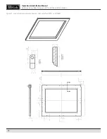
Page 22: ...22 Operation Installation Manual Signature Series Beer Dispensers HP15 HP24 and HP48 models Figure 21 Lock installation wood overlay glass door panel for HP24TS and HP48RT ...

Page 23: ...23 Operation Installation Manual Signature Series Beer Dispensers HP15 HP24 and HP48 models Figure 22 Lock installation wood overlay drawer panel for HP24TS and HP48RT ...

Page 24: ...Overlay panels onto Perlick doors otherwise follow the instructions below OPERATION General The unit is equipped with a state of the art refrigeration system The variable speed compressor automatically changes speed based on system conditions and load The cabinet is equipped with an adjustable digital temperature controller and LED display Freezer units are frost free models meaning the evaporator...

Page 25: ...25 Operation Installation Manual Signature Series Beer Dispensers HP15 HP24 and HP48 models TEMPERATURE CONTROLLER 2011 24 48 72 Cabinet Installation Operation Manual Document No Z2305 27 ...

Page 26: ...the door is opened and closed Length of times the door is left open Style of door installed Door gasket sealing and condition Amount of time the internal light is illuminated Installaion in direct sunlight or near a heart source CLEANING AND OTHER MAINTENANCE CAUTION Shut off electricity to the unit before cleaning the condenser and other routine maintenance To clean stainless steel exterior or in...

Page 27: ... is only on multiple keg units each keg is connected to a valve on the air distributor Single keg is connected directly to the regulator INSTALLING DISPENSING EQUIPMENT Open tapping kit box and become familiar with its components If the dispensing head is going to be mounted on a counter top directly above the refrigerated cabinet have the countertop predrilled using the supplied template or the t...

Page 28: ...way any excess pad Cut away any excess foam that extends into the cabi net that extends into refrigerator 4 If installing a two or three faucet system a CO2 manifold will need to be installed Locate the plastic manifold holding bracket and a 10 x sheet metal screw On the left rear side wall of the beer compartment there is a double row of screws which run vertically Remove one of the two top screw...

Page 29: ...on the regulator counter clockwise one turn Make sure that the valve at the bottom of the regulator where the red hose is connected is in the off position as shown Open the tank valve Watching the secondary pressure gauge turn the regulator adjusting screw clockwise until the pressure is at 10 psig Adjustments can later be made based on flow rates 10 Locate beer faucet s and install onto the dispe...

Page 30: ...30 Operation Installation Manual Signature Series Beer Dispensers HP15 HP24 and HP48 models ...

Page 31: ...inder fitting 3 Replace carbonic washer Part No 157F2P if needed and reattach regulator to filled cylinder 4 Turn CO2 hand valve counterclockwise until fully open Turn regulator shut ff valve to open position 5 Adjust CO2 gas flow as required turning clockwise for higher pressure CAUTION Do not use keg coupler as a handle to lift keg PROPER CO2 HANDLING ALWAYS Connect a regulator reducing valve to...

Page 32: ...APPING A SINGLE VALVE KEG Sankey Be sure beer faucet is in closed position Align keg lug openings on bottom of coupler Turn clockwise 1 4 turn Pull handle out and down Keg is now tapped Open shut off valve on air divider located inside of the cabinet IMPORTANT Be sure to close the gas shut off valve when untapping a keg Single Valve Coupler Step 1 Step 2 Step 3 BEER OUT BOTTOM ADAPTER LUG OPENINGS...

Page 33: ...picking up a strong metallic or plastic flavor as it flows through the system The beer stone will continue to build if the system is not cleaned properly or regularly and can cause drawing problems if it begins to flake off Beer stone is present if one can see a brownish color on the faucet or inner wall of the beer line or tobacco like flakes in the beer BEER SERVICE PROBLEMS Wild Beer Problem Di...

Page 34: ...ucet Open the faucet all the way POURING THE PERFECT GLASS OF BEER STEP TWO Start with a clean glass Place the glass at a 45 angle one inch below faucet Do not let the glass touch the faucet Open the faucet all the way STEP THREE Let the remaining beer run straight down the middle of the glass This ensures proper release of CO2 by producing a 3 4 to 1 foam head STEP FOUR Close the faucet quickly a...

Page 35: ...ng is normal Problem Controller display is flashing P1 There is a thermostat probe failure Problem Controller display is flashing P2 There is an evaporator probe failure Problem Controller display is flashing HA The internal compartment temperature has exceeded the high temperature alarm preset value for over 30 minutes Check to ensure door is closed Check door gasket seal Has warm product been pl...

Page 36: ...e web at www perlick com Call 800 558 5592 for factory assistance on planning installation or product information Write to Perlick Corporation Customer Service Department 8300 West Good Hope Road Milwaukee WI 53223 E mail us at warrantyserv perlick com You need product service Check the model and serial number of your unit located on the label attached to the inside top of the cabinet Then call yo...

Page 37: ...inal purchaser of the Perlick product The above warranty does not apply if Failure of product was due to transportation Product was improperly installed misused abused operating with low voltage wiring not conforming to electrical codes improperly maintained or modified The original Bill of Sale delivery date or serial number cannot be verified Defective parts are not returned for inspection if so...

Page 38: ... or service and the name of the nearest Perlick authorized service representative contact your Perlick dealer distributor or Perlick Corporation s Customer Service Department 8300 West Good Hope Road Milwaukee Wisconsin 53223 call 800 558 5592 E mail us at warrantyserv perlick com or visit our web www bringperlickhome com This limited warranty is in lieu of any other warranty expressed or implied ...

Reviews: