background image

Installation     10

IDS-305F Hardware Installation Guide

Warning

In hazardous location installations, failure to remove from the source prior to completing the 

wiring connections to the alarm relay could cause an electrical arc resulting in a possible explosion.

Warning

Power supply of the equipment must be rated appropriately (see Appendix for specifications) 

with limited power.  Limited power means complying with one of the following requirements.
Class 2 circuit according to Canadian Electrical Code, Part 1, C22.1
Class 2 circuit according to National Electrical Code, NFPA-70
Limited Power Supply (LPS) according to EN/IEC 60950-1;
Limited-energy circuit according to EN/IEC 61010-1

Warning

: If this equipment is used in a manner not specified by the manufacturer, the protection pro-

vided by the equipment may be impaired.

Warning

In case of malfunction or damage, no attempts at repair should be made. Do not dismantle 

the product. All repairs need to be made by a qualified Perle representative.

Warning

Explosion hazard. Do not remove or replace lamps, fuses or plug-in modules (as applicable) 

unless power has been disconnected or the area is free of ignitable concentrations.

Warning

Explosion hazard. Do not disconnect while the circuit is live or unless the area is free of ignit-

able concentrations.

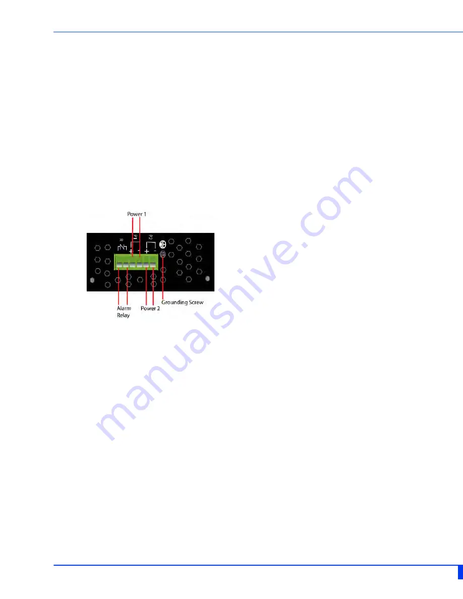
Terminal Block-Power Connectors


Grounding the IDS Switch

Caution

: Minimum temperature rating of the cable to be connected to the field wiring terminals is

105° C.

If your installation requires additional grounding, follow this procedure. 

Grounding the chassis requires the following items:

• One grounding lug (not provided)
• One 12 AWG (3.31 mm²) wire (not provided) 

1

Attach the ground wire to the grounding lug; follow the instructions from the ground lug 
manufacturer.

2

Attach the grounding lug to the chassis and secure with the grounding screw provided. 

Summary of Contents for 07012410

Page 1: ...IDS 305F Hardware Installation Guide Managed Industrial Ethernet Switches Updated September 2016 Revision 1 00 Document Part 5500374 10 www perle com...

Page 2: ...rence when the equipment is operated in a commercial environment This equipment generates uses and can radiate radio frequency energy and if not installed and used in accordance with this hardware gui...

Page 3: ...Connecting the Console Port 11 Connecting Destination Ports 12 Resetting the Switch 13 Booting the Switch 14 Fast Setup Mode 14 Password Recovery 14 Configuring the IDS Switch 15 Appendix A Technical...

Page 4: ...ts IDS switch with attached DIN rail mounting bracket Quick Start Guide Document Conventions This document contains the following conventions Most text is presented in the typeface used in this paragr...

Page 5: ...For more details and for the most up to date list of models please refer to the product pages at www perle com Note xxxxxx denotes the specific type of fiber port installed Refer to the Perle Website...

Page 6: ...4 IDS 305F Hardware Installation Guide Switch Model View IDS 305F Note Fiber Port may appear different depending on the type of fiber port installed...

Page 7: ...after power on System booting Green solid System ready operating normally Green blinking slowly Fast Setup Mode activated port available Green blinking fast Fast Setup Mode activated no port available...

Page 8: ...ter Active redundant port blocked Coupling Link enabled Green flashing Ring Master unable to establish a ring due to missing link on one of the Ring ports Yellow solid Ring Master Active redundant por...

Page 9: ...provide a built in fiber module that provides fiber connectivity at 100 Mb s These fiber ports are available on the switches in a variety of distances wavelengths and connector types Consult the full...

Page 10: ...hernet Port Status Indicators Port Link Speed Green and Yellow LEDs State Description Green 1000 Mbps Green Yellow 100 Mbps Yellow 10 Mbps On solid Port Link Random blinking Port Link and Activity Slo...

Page 11: ...g or office environment the device must be operated exclusively in switch cabinets with fire protection characteristics in accordance with EN 60950 1 Warning The working voltage inputs are designed fo...

Page 12: ...arning In case of malfunction or damage no attempts at repair should be made Do not dismantle the product All repairs need to be made by a qualified Perle representative Warning Explosion hazard Do no...

Page 13: ...e IDS switch has a Normally Closed NC relay with terminals located on the top panel of the unit The IDS switch can be connected to an external powered device such as a siren or light for visual or aud...

Page 14: ...attached devices If auto negotiation is not supported by one or more attached devices the ports can be configured to operate at fixed speeds and duplex settings Warning In hazardous location installat...

Page 15: ...ill perform a complete power down and stay in the powered off state Press the reset button to power the switch on Reset to Factory Default Configuration The IDS 305F can be reset to the Factory defaul...

Page 16: ...Start Guide that came with your IDS switch on how to connect to your switch for the first time Password Recovery When the switch is not in factory default the Fast Setup Mode sequence will activate P...

Page 17: ...re information Web Device Manager The Perle Web Device Manager is an embedded Web based application that provides an easy to use browser interface for managing the switch This interface provides the a...

Page 18: ...connector Fiber 100Base X Fixed Fiber SC ST varies by model Console RJ 45 connector LED Indicators PWR Power Inputs SYS System Status ALR Alarm BC For Future Use RM For Future Use 5 Fiber Port Link A...

Page 19: ...L 60950 1 EN 60950 EN IEC 60950 Industrial Safety UL 61010 1 UL 61010 2 201 EN 61010 1 EN 61010 2 201 EMI EMC FCC 47 Part 15 Class A CISPR22 2008 EN55022 2010 Class A CISPR 24 2010 EN55024 2010 Standa...

Page 20: ...18 IDS 305F Hardware Installation Guide Appendix B Labels IDS 305F IDS 305F XT...

Page 21: ...19 IDS 305F Hardware Installation Guide Appendix C Mechanical Drawings 5 port RJ 45...

Page 22: ...the DIN rail cliponto the bottom of the DIN rail See diagram below Removing the IDS from the DIN Rail 1 The DIN rail attachment clip has a slot at the bottom of the latch that is visible beneath the...

Page 23: ...from the wall to allow room for sliding the wall mount panel between the wall and the screws 5 Once the screws are fixed to the wall insert the four screw heads through the large parts of the keyhole...

Page 24: ...inches on all sides of the IDS switch to provide proper airflowthrough the unit Do not use solvents or cleaning agents on this unit Keep vent holes clear of debris If case gets dirty wipe with a dry...

Page 25: ...evices These Ethernet ports will automatically adjust depending on the type of Ethernet cable used straight through or cross over and the type of device NIC type or HUB Switch type con nected to the p...

Page 26: ...e Single mode 9 125 micron fiber cable Simplex BIDI single strand SC or ST connector Multimode 50 125 or 62 5 125 micron fiber cable Single mode 9 125 micron fiber cable Connect the fiber cable to Por...

Reviews: