Perkins 4012TESI Series User Handbook Manual Download Page 27

INSTRUMENT PANEL

4012/16 Gas, February 1998

23

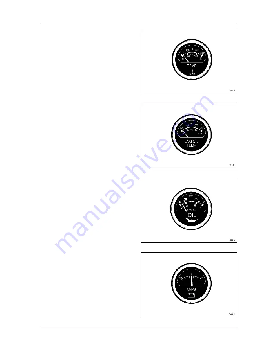
Engine water temperature gauge

(Fahrenheit/Centigrade)

Fig. 6

The coolant temperature during normal
operation should be between 65°C - 85°C
(149°F - 185°F). If the temperature should
rise above 93°C (200°F) for a prolonged
period of time, stop the engine and investi-
gate the cause. The engine should, on the
other hand, not be run at too low a tempera-
ture for long periods either.

Engine oil temperature gauge

(Fahrenheit/

Centigrade)

Fig. 7

The lubricating oil temperature should be
between 80°C - 90°C (176°F - 194°F) when
the engine is hot. If the temperature should
rise above 115°C (240°F), stop the engine
immediately and investigate the cause.

Engine oil pressure gauge Fig. 8

(pounds per square inch/kiloPascal x 100)
The lubricating oil pressure should be
between 300 - 350 kPa (45 - 50 lb/in

2

) when

the engine is hot. If the pressure should
drop below 200 kPa (30 lb/in

2

) at higher

engine speeds than idling, stop the engine
immediately and investigate the cause.

Ammeter (Ampere) Fig. 9

The ammeter indicates at what charging
current the battery is being charged by the
alternator, or to what extent current is taken
from the battery without the battery being
recharged.

Fig. 6

Fig. 7

Fig. 8

Fig. 9

Summary of Contents for 4012TESI Series

Page 1: ...TSL4187E Issue 1 February 1998 User s Handbook Perkins 4012 and 4016 Gas 4012TESI 4016TESI...

Page 2: ...SERIOUS ACCIDENT OR DAMAGE TO THE EQUIPMENT CAUSING INJURY OR DEATH NON COMPLIANCE WITH THESE INSTRUCTIONS AND THOSE INCLUDED IN THE INSTALLATION MANUAL TSL4200 MAY INVALIDATE THE WARRANTY OFFERED WIT...

Page 3: ...table of equivalent engine designations is given on page 2 PERKINS COMPANIES Perkins Group of Companies Perkins Engines Peterborough Ltd Frank Perkins Way Eastfield Peterborough PE1 5NA England Tel 01...

Page 4: ...INTRODUCTION 2 4012 16 Gas February 1998 PERKINS ENGINES STAFFORD ENGINE DESIGNATIONS 4000 SERIES AND SE SERIES EQUIVALENT TERMS 4000 SERIES SE SERIES 4012TESI 12SETCWG 4016TESI 16SETCWG...

Page 5: ...US DUTY CHECKLIST 42 44 FAULT TRACING CHART 45 WIRING DIAGRAMS 4012 16TESI MINNOX WITH CAV STARTER AND PROTECTION SWITCHES 46 4012 16 GAS MINNOX ENGINE STARTING CIRCUIT WITH BUTEC STARTERS AND OPTIONA...

Page 6: ...ooler with separate water pump and cooling circuit lean burn with NOx emission of less than 140 g GJ 11 5 1 compression ratio 4016TESI MINNOX 200 L C 16 cylinder V form 4 stroke gas engine water coole...

Page 7: ...4012TESI MINNOX 4012TESI MINNOX...

Page 8: ...4016TESI MINNOX 4016TESI MINNOX...

Page 9: ...longed and repeated contact with mineral oil will result in the removal of natural oils from the skin leading to dryness irritation and dermatitis The oil also contains potentially harmful contaminant...

Page 10: ...amination of the skin or eyes wash the affected area with a continuous supply of clean water or with a calcium hydroxide solution for 15 60 minutes Obtain immediate medical attention Practical Informa...

Page 11: ...e flywheel with cylinders designated B on the right hand side of the engine NOTE This is NOT the same as the British Standard and ISO designation Valve clearances Exhaust 0 4 mm 0 016 Valve dia mm inl...

Page 12: ...Perkins Part No see Spares Book low pressure gas supply only Gas solenoid valves Not Perkins supply Spit back detector Perkins Part No see Spares Book Manual gas shut off valve Perkins Part No see Sp...

Page 13: ...Max exhaust temperature C after turbocharger See Product Information Manual SAE Size 18 No of teeth on ring gear 156 SAE Size 00 Maximum overhung weight on rear bearing 1700 Kg T V damper 1 x 18 2 x...

Page 14: ...120 C Low oil pressure 2 06 bar 30 lb in 1 93 bar 28 lb in High water temperature 71 C Thermostat 85 C Thermostat 96 C Thermostat 91 C 96 C 100 C 96 C 101 C 105 C Caution The above standard settings...

Page 15: ...V band clamp nuts Schwitzer 7 9 5 Mitsubishi 7 9 5 Garrett 10 13 5 Sandwich plate retaining capscrew if fitted M10 40 57 CRANKCASE AND CRANKSHAFT GROUPS Main bearing bolt M24 580 783 Side bolts main b...

Page 16: ...50 FAN DRIVE Fan driven pulley taper lock bush screw 1 2 BSW 35 50 5 8 BSW 124 170 ALTERNATOR Drive pulley taper lock bush screws 3 8 BSW 14 20 IGNITION SYSTEM Spark plug M18 x 1 5 35 50 Adaptor clam...

Page 17: ...ENERAL TORQUE LOADINGS The following torque loadings are general for metric coarse threads for grade 8 8 steel and do not supersede the figures quoted above Thread Size mm Ibf ft Nm 8 18 25 10 35 50 M...

Page 18: ...st with the selection of suitable oils when presented with the gas analysis TBN Total Base Number NATURAL GAS BIOGAS ENGINES Where gas engines oils are not available please consult Perkins Engines Sta...

Page 19: ...his is addition to the analysis supplied at the order stage and a description of the proposed lubricating oil that is to be used When the engine starts operating it is essential that oil samples are t...

Page 20: ...tack on the additive package in the oil It is essential that the engine breather is functioning effectively Water should be drained from the sump weekly APPROVED LUBRICATING OILS NATURAL GAS ENGINES S...

Page 21: ...ances should an additive containing nitrites borates phosphates chromates nitrates or silicates be used as these materials are not compatible with the materials used in the cooling system When mixing...

Page 22: ...3 4 Ethane 6 4 5 5 Hydrogen content not to exceed 0 2 0 1 6 Propane must not exceed 2 1 7 Isobutane content not to exceed 0 2 0 2 8 Normal butane not to exceed 0 2 0 2 9 Normal pentane and higher frac...

Page 23: ...t in severe damage to the engine refer to page 18 Providing that the actual gas being used meets with the above conditions then the engine need only be derated for altitude and ambient temperature con...

Page 24: ...TURBOCHARGER Before starting the engine for the first time or if it has been stood idle for more than three months the turbocharger bearings should be primed Ensure that the gas supply is turned off a...

Page 25: ...preventative must be used Refer to page 17 After installation and before the first start remove the radiator cap Fig 4 by rotating it anti clockwise Fill the cooling system with the required coolant...

Page 26: ...uments are duplicated giving readings for A and B bank see Fig 5 1 Battery charging rate 2 Coolant temperature A bank 3 Lubricating oil temperature A bank 4 Lubricating oil pressure A bank 5 Taco and...

Page 27: ...should be between 80 C 90 C 176 F 194 F when the engine is hot If the temperature should rise above 115 C 240 F stop the engine immediately and investigate the cause Engine oil pressure gauge Fig 8 po...

Page 28: ...ed at engine idling speed Exhaust temperature gauge optional Temperature range 20 800 C The gauge shows readings of turbine outlet temperature and is switched from A to B bank using the button 1 see F...

Page 29: ...Low cranking speed 3 6 2 Try again once more only commencing with 3 2 above 3 7 When engine is running check oil pressure warm engine through and apply the load 3 8 Check engine condition at full loa...

Page 30: ...enoid valves and governor DO NOT press the red stop button for normal stopping procedure If the ignition is switched off the system will be left full of gas and must be purged Excessive running of the...

Page 31: ...UT NO YES ENERGISE GAS VALVES IGNITION CONTINUE CRANKING CRANK FOR 3 SECONDS PURGE SYSTEM YES YES NO NO HAS ENGINE STARTED FAIL TO START LOCKOUT MAX CRANKING TIME REACHED DE ENERGISE STARTER MOTOR ENG...

Page 32: ...rade as that already in the engine to bring the oil level up to the top mark Always replace the filler plug immediately replenishment is completed COOLANT LEVEL With the engine stopped remove the radi...

Page 33: ...ired oil FENNER TAPE LOCK BUSHES MAINTENANCE INSTRUCTIONS Experience has shown that taper lock bushes as fitted in the fan pulleys and battery alternator driven pulley can work loose shortly after bei...

Page 34: ...ntrifugal filter see page 33 ENGINE ALTERNATOR DRIVE BELT Remove the small mesh guard 1 around the alternator The toothed belt used to drive the alternator relies on tooth engagement to transmit to lo...

Page 35: ...adjuster bolts and operate the jockey pulley lever Moving the jockey pulley lever outwards will tension the belts and inwards will slacken the belts The correct tension is obtained by measur ing the d...

Page 36: ...the top cover and withdraw the two wire mesh elements and wash thoroughly using a suitable cleaning agent Shake as dry as possible finally blow dry with an compressed air Refit the elements into the...

Page 37: ...and wipe clean Ensure that all rotor components are thoroughly cleaned and free from deposits of dirt before reassembling the rotor Failure to do so could cause an out of balance condition which will...

Page 38: ...ilter prior to removal Wipe clean the sealing faces and threaded bosses of the oil header Smear engine oil on the captive rubber sealing ring and carefully screw each new filter up to the oil header u...

Page 39: ...s essential that they are reconnected correctly to avoid unfiltered oil getting into the engine See Fig 24 on page 36 Failure to change fil ters when due can also lead to trouble from unfiltered oil C...

Page 40: ...er with clean oil before fitting Turning the valve so that the leg points to the right puts the left hand filter out of service so that this one can now be exchanged for a new filter canister The valv...

Page 41: ...d hose connection from the filter outlet to the turbocharger intake are sealed airtight FILTER ELEMENT SERVICE Clean the exterior of the filter housing and then carefully remove the element Inspect th...

Page 42: ...suitable cleaning agent shake of excess solvent and blow dry with compressed air Clean any oil sludge deposits from the filter body re assemble and fit to engine The breather valve 2 is mounted at th...

Page 43: ...arter motor hole in the flywheel housing see Fig 30 Using a socket and ratchet wrench press against the spring loaded bolt head until the pinion engages with the flywheel gear then crank the engine to...

Page 44: ...With both bridge pieces equalised check the valve clearance of 0 4 mm 0 016 inlet and exhaust using a feeler gauge 1 If adjustment is required loosen the lock nut 2 and using the adjuster screw 3 set...

Page 45: ...VALVES ROCKING ON CYLINDER NO SET BRIDGE PIECE AND VALVE CLEARANCE ON CYLINDER NO A1 A8 A8 A1 B1 B8 B8 B1 A3 A6 A6 A3 B3 B6 B6 B3 A7 A2 A2 A7 B7 B2 B2 B7 A5 A4 A4 A5 B5 B4 B4 B5 A1 A8 A1 A8 B1 B8 B1 B...

Page 46: ...ange Clean Change For leaks and oil pressure Engine oil level Full flow filters normal or change over Engine oil Crankcase Breather and centrifugal oil filter if fitted Closed circuit crankcase breath...

Page 47: ...tor elements Cooling Check Change Grease Change Clean For radiator air restriction Operation of coolant heater Hoses and connections for leaks Coolant level and operating temperature Antifreeze inhibi...

Page 48: ...tor elements Clean Centrifugal lubricating oil filter First 250 hours and then EVERY 400 HOURS Check Front and rear crankshaft oil seals Cooling Check Change Grease For radiator air restriction Operat...

Page 49: ...4012 4016 GAS ENGINES FAULT TRACING CHART 4012 16 Gas February 1998 45 Fig 34...

Page 50: ...r temp 9 Oil press 10 All fault switches close on a fault One side of all fault switches are identical For the engine to run immediately on depressing start button Gov must be fed 24 volt ve To stop t...

Page 51: ...4012 16 Gas February 1998 47 Key Fig 36 1 Charging alternator 2 Ammeter 3 Oil press 4 Oil temp 5 Water temp 6 Tacho 7 Oil press 8 Oil temp 9 Water temp 10 Gauge senders 11 Oil press switch 12 No 1 St...

Page 52: ...ck up 5 Engine fitted emergency stop button 6 H T Leads 7 Spark plugs 8 Ignition coils 9 Firing order 10 Fused terminals 11 Engine fitted terminal box 12 Heinzmann actuator A bank left 13 Heinzmann ac...

Page 53: ...plug 3 6 Pin plug 4 Pick up 5 Engine fitted emergency stop button 6 H T Leads 7 Spark plugs 8 Magnetic disc 9 Ignition coils 10 Terminal box 11 Magnetic pick up 12 Engine flywheel 13 Heinzmann actuat...

Page 54: ...e on the same fault channel 2 Manifold out of balance switch gauges can be earth return type 9 Left right banks engine fault switches 10 Water temp 11 Oil press 12 Left right banks manifold out of bal...

Page 55: ...ck up 5 Engine fitted emergency stop button 6 H T Leads 7 Spark plugs 8 Ignition coils 9 Firing order 10 Fused terminals 11 Heinzmann actuator A bank left 12 Heinzmann actuator B bank right 13 Magneti...

Page 56: ...plug 4 Pick up 5 Engine fitted emergency stop button 6 HT Leads 7 Spark plugs 8 Ignition Coils 9 Magnetic Disc 10 Heinzmann actuator A bank left 11 Heinzmann actuator B bank right 12 Magnetic pick up...

Page 57: ...1998 Perkins Engines Company Limited All Rights Reserved...

Reviews: