background image

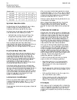
By using the test methods “ASTM D5453, ASTM
D2622, or ISO 20846 ISO 20884”, the content of

sulfur in low sulfur diesel (LSD) fuel must be below
500 PPM 0.05%. By using the test methods “ASTM
D5453, ASTM D2622, or ISO 20846 ISO 20884”, the

content of sulfur in ultra low sulfur (ULSD) fuel must
be below 15 PPM 0.0015%. The use of LSD fuel and

the use of ULSD fuel are acceptable provided that
the fuels meet the minimum requirements that are
stated in table . The lubricity of these fuels must not
exceed wear scar diameter of 0.52 mm

(0.0205 inch). The fuel lubricity test must be
performed on a HFRR, operated at 60 °C (140 °F).
Refer to “ISO 12156-1 ”.

In some parts of the world and for some applications,
high sulfur fuels above 0.5% by mass might only be
available. Fuel with very high sulfur content can
cause engine wear. High sulfur fuel will have a
negative impact on emissions of particulates. High
sulfur fuel can be used provided that the local
emissions legislation will allow the use. High sulfur
fuel can be used in countries that do not regulate
emissions.

When only high sulfur fuels are available, it will be
necessary that high alkaline lubricating oil is used in
the engine or that the lubricating oil change interval is
reduced. Refer to this Operation and Maintenance
Manual, “Fliud Recommendations (Genernal
Lubrication Information)” for information on sulfur in
fuel.

Lubricity

This is the capability of the fuel to prevent pump
wear. The fluid's lubricity describes the ability of the
fluid to reduce the friction between surfaces that are

under load. This ability reduces the damage that is
caused by friction. Fuel injection systems rely on the
lubricating properties of the fuel. Until fuel sulfur limits
were mandated, the fuel's lubricity was generally
believed to be a function of fuel viscosity.

The lubricity has particular significance to the current
low viscosity fuel, low sulfur fuel and low aromatic
fossil fuel. These fuels are made in order to meet

stringent exhaust emissions. A test method for
measuring the lubricity of diesel fuels has been
developed and the test is based on the HFRR
method that is operated at 60 °C (140 °F). Refer to
“ISO 12156 part 1 and CEC document F06-A-96” for
the test method.

Lubricity wear scar diameter of 0.52 mm
(0.0205 inch) MUST NOT be exceeded. The fuel
lubricity test must be performed on a HFRR,
operated at 60 °C (140 °F). Refer to “ISO 12156-1 ”.

Fuel additives can enhance the lubricity of a fuel.
Contact your fuel supplier for those circumstances
when fuel additives are required. Your fuel supplier
can make recommendations for additives to use and

for the proper level of treatment.

Distillation

This is an indication of the mixture of different

hydrocarbons in the fuel. A high ratio of light weight
hydrocarbons can affect the characteristics of
combustion.

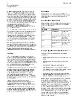
Classification of the Fuels

Diesel engines have the ability to burn a wide variety
of fuels. These fuels are divided into four general
groups: Ref to table 10

Table 10

Fuel Groups

Classification

Group 1

Preferred fuels

Full life of the
Product

Group 2

Permissible fuels with
an appropriate fuel
additive

These fuels MAY
cause reduced en-
gine life and
performance

Group 3

Permissible fuels with
an appropriate fuel
additive

These fuels WILL
cause reduced en-
gine life and
performance

Group 4

Biodiesel

Group 1 Specifications (Preferred Fuels)

This group of fuel specifications is considered
acceptable:

• EN590 DERV Grade A, B, C, E, F, Class, 0, 1, 2, 3

and 4

• “BS2869 Class A2” Off-Highway Gas Oil Red

Diesel

• “ASTM D975”, Class 1D and Class 2D

• “JIS K2204 Grades 1,2,3 and Special Grade 3”

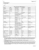
This grade of fuel must meet the minimum lubricity
requirements that are stated in table 9 .

• 5% FAME to “EN14214” can be mixed with the

fuel that meets the requirements that are stated in
table 9 . This blend is commonly known as B5.

Note:

The use of LSD fuel and the use of ULSD fuel

is acceptable provided that the fuels meet the
minimum requirements that are stated in table . The
lubricity of these fuels must not exceed wear scar
diameter of 0.52 mm (0.0205 inch). The lubricity test
must be performed on a HFRR, operated at 60 °C
(140 °F). Refer to “ISO 12156-1 ”. By using the test
methods “ASTM D5453, ASTM D2622, or ISO 20846
ISO 20884”, the content of sulfur in LSD fuel must be
below 500 PPM 0.05%. By using the test methods
“ASTM D5453, ASTM D2622, or ISO 20846 ISO
20884”, the content of sulfur in ULSD fuel must be
below 15 PPM 0.0015%.

58

SEBU8119-04

Maintenance Section
Fuel Specification

Summary of Contents for 1106D

Page 1: ...Operation and Maintenance Manual 1106D Industrial Engine PJ Engine SEBU8119 04 en us January 2021 ...

Page 2: ...ormation that was available at the time that the publication was written The specifications torques pressures measurements adjustments illustrations and other items can change at any time These changes can affect the service that is given to the product Obtain the complete and most current information before you start any job Perkins dealers or Perkins distributors have the most current informatio...

Page 3: ...18 Electrical System 18 Engine Electronics 19 Product Information Section General Information 20 Model Views 21 Product Identification Information 24 Operation Section Lifting and Storage 26 Gauges and Indicators 29 Features and Controls 30 Engine Diagnostics 38 Engine Starting 42 Engine Operation 44 Engine Stopping 45 Cold Weather Operation 47 Maintenance Section Refill Capacities 51 Maintenance ...

Page 4: ...s manual Whenever a question arises regarding your engine or this manual please consult with your Perkins dealer or your Perkins distributor for the latest available information Safety This safety section lists basic safety precautions In addition this section identifies hazardous warning situations Read and understand the basic precautions listed in the safety section before operating or performi...

Page 5: ...r the engine as a convenient reminder Perkins also recommends that a maintenance record be maintained as part of the permanent record of the engine Your authorized Perkins dealer or your Perkins distributor can assist you in adjusting your maintenance schedule to meet the needs of your operating environment Overhaul Major engine overhaul details are not covered in the Operation and Maintenance Man...

Page 6: ...esive that secures the warning signs The warning signs that are loosened could drop off of the engine Replace any warning sign that is damaged or missing If a warning sign is attached to a part of the engine that is replaced install a new warning sign on the replacement part Your Perkins distributor can provide new warning signs 1 Universal Warning Do not operate or work on this equipment unless y...

Page 7: ...ning Do not use aerosol types of starting aids such as ether Such use could result in an explosion and personal injury Illustration 3 g01154809 Typical example The ether warning label 2 is located on the cover of the inlet manifold SEBU8119 04 7 Safety Section Safety Messages ...

Page 8: ... high pressure fuel may cause fluid penetration and burn hazards High pressure fuel spray may cause a fire hazard Failure to follow these inspection maintenance and service in structions may cause personal injury or death Illustration 5 g01154858 Typical example 8 SEBU8119 04 Safety Section Safety Messages ...

Page 9: ...that are not understood Use the proper tools Replace any equipment that is damaged or repair the equipment For initial start up of a new engine or for starting an engine that has been serviced make provisions to stop the engine if an overspeed occurs The stopping of the engine may be accomplished by shutting off the fuel supply and or the air supply to the engine Ensure that only the fuel supply l...

Page 10: ...llecting fluids Only use the tools that are suitable for containing fluids and equipment that is suitable for containing fluids Obey all local regulations for the disposal of liquids Static Electricity Hazard when Fueling with Ultra low Sulfur Diesel Fuel The removal of sulfur and other compounds in ultra low sulfur diesel fuel ULSD fuel decreases the conductivity of ULSD and increases the ability...

Page 11: ...erials that may contain or have come into contact with hexavalent chromium Stay away from areas that might have hexavalent chromium particles in the air Asbestos Information Perkins equipment and replacement parts that are shipped from Perkins engine company limited are asbestos free Perkins recommends the use of only genuine Perkins replacement parts Use the following guidelines when you handle a...

Page 12: ...t the coolant level after the engine has stopped and the engine has been allowed to cool Ensure that the filler cap is cool before removing the filler cap The filler cap must be cool enough to touch with a bare hand Remove the filler cap slowly to relieve pressure Cooling system conditioner contains alkali Alkali can cause personal injury Do not allow alkali to contact the skin the eyes or the mou...

Page 13: ...sed for storing flammable materials Do not expose the engine to any flame Exhaust shields if equipped protect hot exhaust components from oil or fuel spray in a line a tube or a seal failure Exhaust shields must be installed correctly Do not weld on lines or tanks that contain flammable fluids Do not flame cut lines or tanks that contain flammable fluid Clean any such lines or tanks thoroughly wit...

Page 14: ...a fire extinguisher is available Be familiar with the operation of the fire extinguisher Inspect the fire extinguisher and service the fire extinguisher regularly Obey the recommendations on the instruction plate Lines Tubes and Hoses Do not bend high pressure lines Do not strike high pressure lines Do not install any lines that are damaged Leaks can cause fires Consult your Perkins dealer or your...

Page 15: ...dismount the engine only at locations that have steps and or handholds Do not climb on the engine and do not jump off the engine Face the engine in order to mount the engine or dismount the engine Maintain a three point contact with the steps and handholds Use two feet and one hand or use one foot and two hands Do not use any controls as handholds Do not stand on components which cannot support yo...

Page 16: ...Do not deflect the high pressure fuel lines Do not bend or strike the high pressure fuel lines Deformation or damage of the high pressure fuel lines may cause a point of weakness and potential failure Do not check the high pressure fuel lines with the engine or the starting motor in operation After the engine has stopped allow 60 seconds to pass in order to allow the pressure to be purged before a...

Page 17: ...otective guards and all protective covers must be installed if the engine must be started in order to perform service procedures To help prevent an accident that is caused by parts in rotation work around the parts carefully Do not bypass the automatic shutoff circuits Do not disable the automatic shutoff circuits The circuits are provided in order to help prevent personal injury The circuits are ...

Page 18: ... the engine i02234878 Electrical System Never disconnect any charging unit circuit or battery circuit cable from the battery when the charging unit is operating A spark can cause the combustible gases that are produced by some batteries to ignite To help prevent sparks from igniting combustible gases that are produced by some batteries the negative cable should be connected last from the external ...

Page 19: ...o not come in contact with the harness connector for the elec tronic unit injectors while the engine is operating Failure to follow this instruction could result in personal injury or death This engine has a comprehensive programmable Engine Monitoring System The Electronic Control Module ECM has the ability to monitor the engine operating conditions If any of the engine parameters extend outside ...

Page 20: ... 3 Disconnect the J1 P1 connectors from the ECM Move the harness to a position that will not allow the harness to accidentally move back and make contact with any of the ECM pins Illustration 17 g00765012 Use the example above The current flow from the welder to the ground clamp of the welder will not cause damage to any associated components 1 Engine 2 Welding rod 3 Keyswitch in the OFF position ...

Page 21: ...s are identified on the following illustrations Illustration 18 g01391892 Front left engine view 1 Fuel manifold Rail 2 Canister for the crankcase breather 3 Electronic control module 4 P2 connector 5 Secondary fuel filter 6 Hand primer 7 Primary fuel filter 8 Oil sampling valve 9 Oil filter 10 Fuel pump 11 Water pump 12 Damper 13 Fan 14 Fan pulley 15 Belt tensioner SEBU8119 04 21 Product Informat...

Page 22: ... Description The 1106 Electronic Engine model PJ is designed for the following applications machine and industrial mobile equipment The engine is available in the following type of aspiration Turbocharged aftercooled Four stroke cycle In line 6 cylinder Engine Specifications Note The front end of the engine is opposite the flywheel end of the engine The left and the right sides of the engine are d...

Page 23: ...t the engine systems are functioning correctly The operator will be alerted to the condition by a Stop or Warning lamp Under certain conditions the engine horsepower and the vehicle speed may be limited The electronic service tool may be used to display the diagnostic codes There are three types of diagnostic codes active logged and event Most of the diagnostic codes are logged and stored in the E...

Page 24: ...read by using the electronic service tool Serial Number Plate 1 The engine serial number plate is located on the left side of the cylinder block to the rear of the front engine mounting Illustration 22 g01094203 Serial number plate i02164876 Reference Numbers Information for the following items may be needed to order parts Locate the information for your engine Record the information in the approp...

Page 25: ...or Belt i02894856 Emissions Certification Film Label for compliant engines Typical examples of emissions labels Illustration 23 g01440937 SEBU8119 04 25 Product Information Section Emissions Certification Film ...

Page 26: ...ents are damaged Use a hoist to remove heavy components Use an adjustable lifting beam to lift the engine All supporting members chains and cables should be parallel to each other The chains and cables should be perpendicular to the top of the object that is being lifted Some removals require lifting the fixtures to obtain correct balance and safety To remove the engine ONLY use the lifting eyes t...

Page 27: ... on the cylinder walls Rust on the cylinder walls will cause increased engine wear and a reduction in engine service life Perkins are not responsible for damage which may occur when an engine is in storage after a period in service Your Perkins dealer or your Perkins distributor can assist in preparing the engine for extended storage periods If an engine is out of operation and if use of the engin...

Page 28: ...l Mark on the engine oil level gauge with new clean lubricating oil Add 1762811 POWERPART Lay Up 2 to the oil in order to protect the engine against corrosion If 1762811 POWERPART Lay Up 2 is not available use a preservative of the correct specification instead of the lubricating oil If a preservative is used this must be drained completely at the end of the storage period and the oil pan must be ...

Page 29: ...ad is stable and the gauge reading changes perform the following procedure 1 Remove the load 2 Stop the engine 3 Check and maintain the oil level Jacket Water Coolant Temperature Typical temperature range is 83 to 95 C 181 4 to 171 F The maximum allowable temperature at sea level with the pressurized cooling system at 48 kPa 7 psi is 103 C 217 4 F Higher temperatures may occur under certain condit...

Page 30: ...m If the Shutdown mode has been selected and the warning indicator activates engine shutdown may take as little as 20 seconds from the time the warning indicator is activated Depending on the application special precautions should be taken to avoid personal injury The engine can be re started following shutdown for emergency ma neuvers if necessary NOTICE The Engine Monitoring System is not a guar...

Page 31: ...ccurs The engine can be restarted after a shutdown for use in an emergency A shutdown of the engine may occur in as little as 20 seconds The engine can be restarted after a shutdown for use in an emergency However the cause of the initial shutdown may still exist The engine may shut down again in as little as 20 seconds If there is a signal for low oil pressure or for coolant temperature there wil...

Page 32: ... manifold air temperature sensor 3 Intake manifold pressure sensor 4 Fuel pressure sensor 5 Electronic control module ECM 6 Oil pressure sensor 7 Primary position sensor 8 Secondary position sensor 32 SEBU8119 04 Operation Section Sensors and Electrical Components ...

Page 33: ... 1 Coolant temperature sensor 2 Intake manifold air temperature sensor 3 Intake manifold pressure sensor 4 Fuel pressure sensor 5 Electronic control module ECM SEBU8119 04 33 Operation Section Sensors and Electrical Components ...

Page 34: ...s taken by the Engine Control Module ECM 5 in response to a condition that can damage the engine These conditions are identified by the ECM from the signals that are produced from the following sensors Coolant Temperature Sensor Intake manifold Air Temperature Sensor Intake manifold Pressure Sensor Fuel Pressure Sensor Engine Oil Pressure Sensor Primary Speed Timing Sensor Secondary Speed Timing S...

Page 35: ...Low Oil Pressure Warning The setpoint for the low pressure warning is dependent upon the engine speed The fault will be active and logged only if the engine has been running for more than 8 seconds Very Low Oil Pressure Warning The very low oil pressure setpoint is dependent upon the engine speed If the DERATE mode of the engine monitoring system is selected the ECM 5 will derate the engine power ...

Page 36: ... ECM An event code is created by the ECM The ECM will send a signal in order to illuminate the lamp Your engine may be equipped with the following sensors or switches Coolant level The low coolant level switch indicates when the coolant level is low Coolant temperature The coolant temperature sensor indicates high jacket water coolant temperature Intake manifold air temperature The intake manifold...

Page 37: ...ghts will be illuminated for two seconds after the keyswitch is operated Replace suspect bulbs immediately Refer to Troubleshooting for more information i02237393 Overspeed An overspeed condition is detected by the Electronic Control Module ECM The event code will be logged if the engine speed exceeds 3000 rpm The DIAGNOSTIC lamp will indicate a diagnostic active code The diagnostic active code wi...

Page 38: ...onic Service Tools for more information i02857828 Diagnostic Flash Code Retrieval Diagnostic Lamp Use the DIAGNOSTIC lamp or an electronic service tool to determine the diagnostic flash code Use the following procedure to retrieve the flash codes if the engine is equipped with a DIAGNOSTIC lamp 1 Move the keyswitch from the on off two times within three seconds A flashing YELLOW lamp indicates a 3...

Page 39: ... Secondary Engine Speed Timing Sensor Fault X 143 Engine Timing Calibration Fault X X 144 Engine Operation Mode Se lector Switch Fault X X 151 High Air Filter Restriction X X 154 Throttle Position sensor Fault X X 155 Secondary Throttle Position sensor Fault X X 157 Engine Oil Pressure Sensor Fault X X 159 Fuel Rail Pressure Sensor Fault X X 162 Fuel Rail Pressure Valve Solenoid Fault X X X 168 En...

Page 40: ...e following logged faults can not be cleared from the memory of the ECM without using a factory password Overspeed low engine oil pressure and high engine coolant temperature i02651197 Engine Operation with Active Diagnostic Codes If a diagnostic lamp illuminates during normal engine operation the system has identified a situation that is not within the specification Use the electronic service too...

Page 41: ...hoot the situation The information can also be used for future reference For more information on diagnostic codes refer to the Troubleshooting Guide for this engine SEBU8119 04 41 Operation Section Engine Operation with Intermittent Diagnostic Codes ...

Page 42: ... module ECM will control the engine speed during start up Starting the Engine 1 Disengage any equipment that is driven by the engine 2 Turn the keyswitch to the RUN position Leave the keyswitch in the RUN position until the warning light for the glow plugs is extinguished 3 When the warning light for the glow plugs is extinguished turn the keyswitch to the START position in order to engage the ele...

Page 43: ...t be replaced or charged to the proper voltage with a battery charger after the engine is stopped Many batteries which are considered unusable are still rechargeable Refer to Operation and Maintenance Manual Battery Replace and Testing and Adjusting Manual Battery Test i02330138 After Starting Engine Note In ambient temperatures from 0 to 60 C 32 to 140 F the warm up time is approximately three mi...

Page 44: ... maximum fuel efficiency in all applications Follow the recommended procedures in order to attain optimum performance for the life of the engine Avoid spilling fuel Fuel expands when the fuel is warmed up The fuel may overflow from the fuel tank Inspect fuel lines for leaks Repair the fuel lines as needed Be aware of the properties of the different fuels Use only the recommended fuels Avoid unnece...

Page 45: ...e the engine for at least 10 minutes in order to allow the engine oil to return to the oil pan Contact with high pressure fuel may cause fluid penetration and burn hazards High pressure fuel spray may cause a fire hazard Failure to follow these inspection maintenance and service in structions may cause personal injury or death After the engine has stopped you must wait for 60 seconds in order to a...

Page 46: ...correct corrosion protection Add the correct coolant water mixture if necessary Perform all required periodic maintenance on all driven equipment This maintenance is outlined in the instructions from the OEM 46 SEBU8119 04 Operation Section After Stopping Engine ...

Page 47: ...r Cold Weather Operation If the engine will start operate the engine until a minimum operating temperature of 81 C 177 8 F is achieved Achieving operating temperature will help prevent the intake valves and exhaust valves from sticking The cooling system and the lubrication system for the engine do not lose heat immediately upon shutdown This means that an engine can be shut down for a period of t...

Page 48: ...dations for Coolant Warm Up Warm up an engine that has cooled below normal operating temperatures due to inactivity The warm up should be performed before the engine is returned to full operation During operation in very cold temperature conditions damage to engine valve mechanisms can result from engine operation for short intervals This action can happen if the engine is started and the engine i...

Page 49: ...nt i07818744 Fuel and the Effect from Cold Weather Note Only use grades of fuel that are recommended by Perkins Refer to this Operation and Maintenance Manual Fluid Recommendations Properties of the diesel fuel can have a significant effect on the engine cold start capability It is critical that the low temperature properties of diesel fuel are acceptable for the minimum ambient temperature the en...

Page 50: ... and or sediment from being pumped from the fuel storage tank and into the engine fuel tank Fuel Filters A primary fuel filter is installed between the fuel tank and the engine fuel inlet After you change the fuel filter always prime the fuel system in order to remove air bubbles from the fuel system Refer to the Operation and Maintenance Manual in the Maintenance Section for more information on p...

Page 51: ...oling System Table 5 Engine Refill Capacities Compartment or System Liters Engine Only 9 L 1 9797 Imp gal External System Per OEM 1 continued Table 5 contd 1 The External System includes a radiator or an expansion tank with the following components heat exchanger and piping Re fer to the OEM specifications Enter the value for the capacity of the External System in this row i02663093 Fluid Recommen...

Page 52: ...used to define DHD 1 are similar to the new API CH 4 classification Therefore these oils will also meet the requirements for diesel engines that require low emissions DHD 1 oils are designed to control the harmful effects of soot with improved wear resistance and improved resistance to plugging of the oil filter These oils will also provide superior piston deposit control for engines with either t...

Page 53: ...eteriorates to 50 percent of the original TBN Use the following guidelines for fuel sulfur levels that exceed 1 5 percent Choose an oil with the highest TBN that meets one of these classifications EMA DHD 1 and API CH 4 Reduce the oil change interval Base the oil change interval on the oil analysis Ensure that the oil analysis includes the condition of the oil and a wear metal analysis Excessive p...

Page 54: ...thetic base stock multigrade oil with an 0W viscosity grade or with a 5W viscosity grade Use an oil with a pour point that is lower than 50 C 58 F Perkins recommends the following lubricants for use in cold weather conditions Use a commercial oil that is API CI 4 CI 4 PLUS CH 4 and CG 4 The oil must have one of the following lubricant viscosity grades SAE 0W 20 SAE 0W 30 SAE 0W 40 SAE 5W 30 and SA...

Page 55: ...ations Fuel Specification Glossary ISO International Standards Organization ASTM American Society for Testing and Materials HFRR High Frequency Reciprocating Rig for Lubricity testing of diesel fuels FAME Fatty Acid Methyl Esters CFR Co ordinating Fuel Research LSD Low Sulfur Diesel ULSD Ultra Low Sulfur Diesel RME Rape Methyl Ester SME Soy Methyl Ester EPA Environmental Protection Agency of the U...

Page 56: ...per 100 mL maximum D381 ISO 6246 Lubricity corrected wear scar diameter at 60 C 140 F 7 mm 0 52 maximum D6079 ISO 12156 1 1 This specification includes the requirements for Ultra Low Sulfur Diesel ULSD ULSD fuel will have 15 ppm 0 0015 sulfur Refer to ASTM D5453 ASTM D2622 or ISO 20846 ISO 20884 test methods This specification includes the requirements for Low Sulfur Diesel LSD LSD fuel will have ...

Page 57: ...ing conditions A higher cetane value may be required for operations at high altitudes or in cold weather operations Fuel with a low cetane number can be the root cause of problems during cold start Viscosity Viscosity is the property of a liquid of offering resistance to shear or flow Viscosity decreases with increasing temperature This decrease in viscosity follows a logarithmic relationship for ...

Page 58: ...t 60 C 140 F Refer to ISO 12156 part 1 and CEC document F06 A 96 for the test method Lubricity wear scar diameter of 0 52 mm 0 0205 inch MUST NOT be exceeded The fuel lubricity test must be performed on a HFRR operated at 60 C 140 F Refer to ISO 12156 1 Fuel additives can enhance the lubricity of a fuel Contact your fuel supplier for those circumstances when fuel additives are required Your fuel s...

Page 59: ... SME is the most common biodiesel in the United States This biodiesel is derived from soybean oil Soybean oil or rapeseed oil are the primary feedstocks These fuels are together known as Fatty Acid Methyl Esters FAME Raw pressed vegetable oils are NOTacceptable for use as a fuel in any concentration in compression engines Without esterification these oils gel in the crankcase and the fuel tank The...

Page 60: ... to a maximum of B5 Examples of applications that should limit the use of biodiesel are the following Standby Generator sets and certain emergency vehicles Biodiesel is an excellent medium for microbial contamination and growth Microbial contamination and growth can cause corrosion in the fuel system and premature plugging of the fuel filter The use of conventionalanti microbial additives and the ...

Page 61: ...o an area with below freezing temperatures the cooling system must be either protected to the lowest outside tem perature or drained completely to prevent damage NOTICE Frequently check the specific gravity of the coolant for proper freeze protection or for anti boil protection Clean the cooling system for the following reasons Contamination of the cooling system Overheating of the engine Foaming ...

Page 62: ...ne glycol may also be used In a 1 1 mixture with water ethylene and propylene glycol provide similar protection against freezing and boiling See Tables 13 and 14 Table 13 Ethylene Glycol Concentration Freeze Protection 50 Percent 36 C 33 F 60 Percent 51 C 60 F NOTICE Do not use propylene glycol in concentrations that exceed 50 percent glycol because of propylene gly col s reduced heat transfer cap...

Page 63: ...ntainers of several sizes are available Consult your Perkins distributor for the part numbers ELC Cooling System Maintenance Correct additions to the Extended Life Coolant NOTICE Use only Perkins products for pre mixed or concen trated coolants Mixing Extended Life Coolant with other products re duces the Extended Life Coolant service life Failure to follow the recommendations can reduce cooling s...

Page 64: ...ve ness of the ELC and shortens the ELC service life Use only Perkins Products for premixed or concen trate coolants Failure to follow these recommenda tions can result in shortened cooling system component life ELC cooling systems can withstand contamination to a maximum of ten percent of conventional heavy duty antifreeze or SCA If the contamination exceeds ten percent of the total system capaci...

Page 65: ... to the Operation and Maintenance Manual Maintenance Interval Schedule Maintenance Section Test the concentration of SCA Additions of SCA are based on the results of the test The size of the cooling system determines the amount of SCA that is needed Use the equation that is in Table 19 to determine the amount of Perkins SCA that is required if necessary Table 19 Equation For Adding The SCA To The ...

Page 66: ...nd Sediment Drain 96 Every 250 Service Hours Engine Oil and Filter Change 85 Initial 500 Service Hours Engine Valve Lash Inspect Adjust 85 Every 500 Service Hours Fan Clearance Check 86 Every 500 Service Hours or 1 Year Battery Electrolyte Level Check 70 Cooling System Supplemental Coolant Additive SCA Test Add Crankcase Breather Canister Replace 77 Engine Air Cleaner Element Dual Element Clean Re...

Page 67: ...Hours or 2 Years Cooling System Coolant Commercial Heavy Duty Change 71 Every 4000 Service Hours Aftercooler Core Clean Test 68 Every 12 000 Service Hours or 6 Years Cooling System Coolant ELC Change 73 Commissioning Fan Clearance Check 86 SEBU8119 04 67 Maintenance Section Maintenance Interval Schedule ...

Page 68: ...y can result without following prop er procedure When using pressure air wear a protective face shield and protective clothing Maximum air pressure at the nozzle must be less than 205 kPa 30 psi for cleaning purposes 8 Dry the core with compressed air Direct the air in the reverse direction of the normal flow 9 Inspect the core in order to ensure cleanliness Pressure test the core If necessary rep...

Page 69: ...or long periods of time or if the engine is run for short periods the batteries may not fully charge A battery with a low charge will freeze more easily than a battery with a full charge i02680086 Alternator and Fan Belts Inspect NOTICE Ensure that the engine is stopped before any servic ing or repair is performed To maximize the engine performance inspect the belt 1 for wear and for cracking Repl...

Page 70: ...rged the ammeter reading should be very near zero when the engine is in operation All lead acid batteries contain sulfuric acid which can burn the skin and clothing Always wear a face shield and protective clothing when working on or near batteries 1 Remove the filler caps Maintain the electrolyte level to the FULL mark on the battery If the addition of water is necessary use distilled water If di...

Page 71: ...d Visually inspect the guide roller for damage Ensure that the guide roller can rotate freely Install the belt Refer to Disassembly and Assembly Alternator Belt Remove and Install i02238072 Cooling System Coolant Commercial Heavy Duty Change NOTICE Care must be taken to ensure that fluids are con tained during performance of inspection mainte nance testing adjusting and repair of the product Be pr...

Page 72: ... radiator NOTICE Do not fill the cooling system faster than 5 L 1 3 US gal per minute to avoid air locks Cooling system air locks may result in engine damage 3 Fill the cooling system with clean water Install the cooling system filler cap 4 Start and run the engine at low idle until the temperature reaches 49 to 66 C 120 to 150 F 5 Stop the engine and allow the engine to cool Loosen the cooling sy...

Page 73: ...in ers before opening any compartment or disassem bling any component containing fluids Dispose of all fluids according to Local regulations and mandates NOTICE Keep all parts clean from contaminants Contaminants may cause rapid wear and shortened component life Clean the cooling system and flush the cooling system before the recommended maintenance interval if the following conditions exist The e...

Page 74: ...ol Loosen the cooling system filler cap slowly in order to relieve any pressure Remove the cooling system filler cap Open the drain cock or remove the drain plug on the engine Open the drain cock or remove the drain plug on the radiator Allow the water to drain Flush the cooling system with clean water Fill 1 Close the drain cock or install the drain plug on the engine Close the drain cock or inst...

Page 75: ...l in the coolant recovery tank Maintain the coolant level to COLD FULL mark on the coolant recovery tank Pressurized System Hot coolant can cause seri ous burns To open the cooling system filler cap stop the engine and wait until the cooling system components are cool Loosen the cooling system pressure cap slowly in order to relieve the pressure 2 Loosen filler cap slowly in order to relieve any p...

Page 76: ... cooling system coolant additive Test for SCA Concentration Heavy Duty Coolant Antifreeze and SCA NOTICE Do not exceed the recommended six percent supple mental coolant additive concentration Use a Coolant Conditioner Test Kit in order to check the concentration of the SCA Add the SCA If Necessary NOTICE Do not exceed the recommended amount of supple mental coolant additive concentration Excessive...

Page 77: ... in order to pressure test the filler cap The correct pressure is stamped on the face of the filler cap If the filler cap does not retain the correct pressure install a new filler cap i02788266 Crankcase Breather Canister Replace NOTICE Ensure that the engine is stopped before any servic ing or repair is performed 1 Place a container under canister 2 2 Clean the outside of the canister Use a suita...

Page 78: ...lements with damaged pleats gaskets or seals Dirt entering the engine causes premature wear and damage to engine components Air cleaner elements help to pre vent airborne debris from entering the air inlet NOTICE Never service the air cleaner element with the engine running since this will allow dirt to enter the engine Servicing the Air Cleaner Elements Note The air filter system may not have bee...

Page 79: ...ner Elements Refer to the OEM information in order to determine the number of times that the primary filter element can be cleaned When the primary air cleaner element is cleaned check for rips or tears in the filter material The primary air cleaner element should be replaced at least one time per year This replacement should be performed regardless of the number of cleanings NOTICE Do not tap or ...

Page 80: ... vacuum cleaning the dirty side outside of a primary air cleaner element Note Refer to Inspecting the Primary Air Cleaner Elements Inspecting the Primary Air Cleaner Elements Illustration 43 g00281693 Inspect the clean dry primary air cleaner element Use a 60 watt blue light in a dark room or in a similar facility Place the blue light in the primary air cleaner element Rotate the primary air clean...

Page 81: ...the air cleaner element should be replaced when one of the following conditions occur The yellow diaphragm enters the red zone The red piston locks in the visible position Test the Service Indicator Service indicators are important instruments Check for ease of resetting The service indicator should reset in less than three pushes Check the movement of the yellow core when the engine is accelerate...

Page 82: ... is in the normal operating position in order to obtain a true level indication Note After the engine has been switched OFF wait for 10 minutes in order to allow the engine oil to drain to the oil pan Then check the oil level 1 Maintain the oil level between the ADD mark Y and the FULL mark X on the engine oil dipstick Or maintain the engine oil level between the H and L mark Do not over fill the ...

Page 83: ...particles in the oil i02667766 Engine Oil and Filter Change Hot oil and hot components can cause personal injury Do not allow hot oil or hot components to contact the skin NOTICE Care must be taken to ensure that fluids are con tained during performance of inspection mainte nance testing adjusting and repair of the product Be prepared to collect the fluid with suitable contain ers before opening a...

Page 84: ...art of the preventive maintenance program 2 Cut the oil filter open with a suitable tool Break apart the pleats and inspect the oil filter for metal debris An excessive amount of metal debris in the oil filter may indicate early wear or a pending failure Use a magnet to differentiate between the ferrous metals and the nonferrous metals that are found in the oil filter element Ferrous metals may in...

Page 85: ...erform this procedure in order to ensure that the lubrication system has oil and that the oil filters are filled Inspect the oil filter for oil leaks 3 Stop the engine and allow the oil to drain back to the oil pan for a minimum of ten minutes Illustration 51 g01165836 Y Min mark X Max mark 4 Remove the engine oil level gauge in order to check the oil level Maintain the oil level between the MIN a...

Page 86: ... to cool before measuring adjusting valve lash clearance Ensure that the engine is stopped before measuring the valve lash The engine valve lash can be inspected and adjusted when the temperature of the engine is hot or cold Refer to Systems Operation Testing and Adjusting Engine Valve Lash Inspect Adjust for more information i02683336 Fan Clearance Check There are different types of cooling syste...

Page 87: ... before adjustments and repairs are performed Note Refer to Testing and Adjusting Manual Cleanliness of Fuel System Components for detailed information on the standards of cleanliness that must be observed during ALL work on the fuel system Ensure that all adjustments and repairs are performed by authorized personnel that have had the correct training NOTICE Do not crank the engine continuously fo...

Page 88: ...r repair is performed on the engine fuel lines If necessary perform minor adjustments Repair any leaks from the low pressure fuel system and from the cooling lubrication or air systems Replace any high pressure fuel line that has leaked Refer to Disassembly and assembly Manual Fuel Injection Lines Install If you inspect the engine in operation always use the proper inspection procedure in order to...

Page 89: ... Drain Fuel leaked or spilled onto hot surfaces or electri cal components can cause a fire To help prevent possible injury turn the start switch off when changing fuel filters or water separator elements Clean up fuel spills immediately NOTICE Ensure that the engine is stopped before any servic ing or repair is performed NOTICE The water separator can be under suction during nor mal engine operati...

Page 90: ...s before any service or repair is performed on the engine fuel lines If necessary perform minor adjustments Repair any leaks from the low pressure fuel system and from the cooling lubrication or air systems Replace any high pressure fuel line that has leaked Refer to Disassembly and assembly Manual Fuel Injection Lines Install 1 Turn the fuel supply valve if equipped to the OFF position before per...

Page 91: ...ury turn the start switch off when changing fuel filters or water separator elements Clean up fuel spills immediately Note Refer to Testing and Adjusting Manual Cleanliness of Fuel System Components for detailed information on the standards of cleanliness that must be observed during ALL work on the fuel system After the engine has stopped you must wait for 60 seconds in order to allow the fuel pr...

Page 92: ...Tighten the drain 1 by hand pressure only 5 If equipped remove the wiring harness from the sensor on the bottom of the bowl 3 Illustration 59 g01370722 Typical example 6 Rotate the bowl 3 counterclockwise in order to remove the bowl Remove the O ring seal 2 Clean the bowl 92 SEBU8119 04 Maintenance Section Fuel System Primary Filter Water Separator Element Replace ...

Page 93: ... in order to tighten the canister correctly 9 Remove the cap 8 from the threaded end of the new canister and remove the new O ring seal 7 Install the new O ring seal into the bowl 3 10 Lubricate the O ring seal 7 with clean engine oil Install the bowl onto the new canister Tighten the bowl to 15 N m 11 lb ft 11 If equipped install the wiring harness to the sensor Open the fuel supply valve 12 Remo...

Page 94: ... If necessary perform minor adjustments Repair any leaks from the low pressure fuel system and from the cooling lubrication or air systems Replace any high pressure fuel line that has leaked Refer to Disassembly and assembly Manual Fuel Injection Lines Install 1 Ensure that the fuel supply valve if equipped is in the OFF position Place a suitable container under the fuel filter in order to catch a...

Page 95: ...pair any leaks from the low pressure fuel system and from the cooling lubrication or air systems Replace any high pressure fuel line that has leaked Refer to Disassembly and assembly Manual Fuel Injection Lines Install 1 Ensure that the fuel supply valve if equipped is in the OFF position Place a suitable container under the fuel filter in order to catch any fuel that might spill Clean up any spil...

Page 96: ...revent condensation Do not fill the tank to the top The fuel expands as the fuel gets warm The tank may overflow Some fuel tanks use supply pipes that allow water and sediment to settle below the end of the fuel supply pipe Some fuel tanks use supply lines that take fuel directly from the bottom of the tank If the engine is equipped with this system regular maintenance of the fuel system filter is...

Page 97: ...rain the coolant into a suitable clean container The coolant can be reused 3 Drain the coolant from the cooling system to a level that is below the hose that is being replaced 4 Remove the hose clamps 5 Disconnect the old hose 6 Replace the old hose with a new hose 7 Install the hose clamps with a torque wrench Note For the correct coolant see this Operation and Maintenance Manual Fluid Recommenda...

Page 98: ...rder to determine if the engine is operating within the defined parameters Severe service operation can accelerate component wear Engines that operate under severe conditions may need more frequent maintenance intervals in order to ensure maximum reliability and retention of full service life Due to individual applications it is not possible to identify all of the factors which can contribute to s...

Page 99: ...spection of the turbocharger can minimize unscheduled downtime A visual inspection of the turbocharger can also reduce the chance for potential damage to other engine parts Removal and Installation For options regarding the removal installation and replacement consult your Perkins dealer or your Perkins distributor Refer to the Disassembly and Assembly Turbocharger Remove and Turbocharger Install ...

Page 100: ...n recommended until the leak is found or fixed or until the suspicion of a leak is proved to be unwarranted NOTICE Accumulated grease and or oil on an engine is a fire hazard Remove the accumulated grease and oil Re fer to this Operation and Maintenance Manual En gine Clean for more information Ensure that the cooling system hoses are correctly clamped and that the cooling system hoses are tight C...

Page 101: ...f the fuel system for leaks Look for loose fuel line clamps Drain the water and the sediment from the fuel tank on a daily basis in order to ensure that only clean fuel enters the fuel system Inspect the wiring and the wiring harnesses for loose connections and for worn wires or frayed wires Check for any loose tie wraps or missing tie wraps Inspect the ground strap for a good connection and for g...

Page 102: ...seous emission standards that are prescribed by the law at the time of manufacture This engine may be covered by an Emissions Warranty Consult your authorized Perkins dealer or distributor to determine if your engine is emissions certified and if your engine is subject to an Emissions Warranty 102 SEBU8119 04 Warranty Section Warranty Information ...

Page 103: ...reather Canister Replace 77 Crushing Prevention and Cutting Prevention 14 D Diagnostic Flash Code Retrieval 38 Diagnostic Lamp 38 Diagnostic Lamp 38 Driven Equipment Check 77 E Electrical System 18 Grounding Practices 18 Emergency Stopping 45 Emissions Certification Film 25 Label for compliant engines 25 Emissions Warranty Information 102 Engine Clean 78 Engine Air Cleaner Element Dual Element Cle...

Page 104: ... 50 Fuel Filters 50 Fuel Heaters 50 Fuel Tanks 50 Fuel System Prime 87 Electric Fuel Priming Pump 88 Hand Fuel Priming Pump 88 Fuel System Primary Filter Water Separator Element Replace 90 Type One Filter 90 Type Two Filter 91 Fuel System Primary Filter Water Separator Drain 89 Fuel System Secondary Filter Replace 94 Type One Filter 94 Type Two filter 95 Fuel Tank Water and Sediment Drain 96 Drain...

Page 105: ...ectronic Control Module 5 35 Engine Oil Pressure Sensor 6 35 Failure of Sensors 34 Fuel Pressure Sensor 4 35 Intake Manifold Air Temperature Sensor 2 35 Intake Manifold Pressure Sensor 3 35 Primary Speed Timing Sensor 7 35 Programmable Monitoring System PMS 34 Secondary Speed Timing Sensor 8 36 Sensor Locations 31 Severe Service Application Check 98 Environmental Factors 98 Incorrect Maintenance P...

Page 106: ......

Page 107: ...Maintenance Manual Delivery Date Product Information Model Product Identification Number Engine Serial Number Transmission Serial Number Generator Serial Number Attachment Serial Numbers Attachment Information Customer Equipment Number Dealer Equipment Number Dealer Information Name Branch Address Dealer Contact Phone Number Hours Sales Parts Service ...

Page 108: ...SEBU8119 2021 Perkins Engines Company Limited All Rights Reserved 108 January 2021 ...

Reviews: