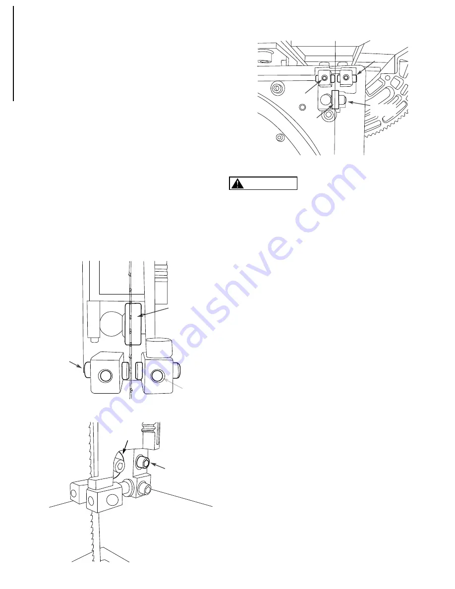
Performax 240-3731 Owner'S Manual Download Page 8

ADJUST BLADE GUIDES

Refer to Figure 9 to 11

•   

Blade guides should not be in contact with the blade 

   when not in operation.

•   

Adjust the blade guides after the blade tracking and 

   blade tension have been properly adjusted.

•   

The blade guide supports the blade with bearings on the 

   real and guide pins on both sides. They all should be 

   adjusted to be 0.016” inches away from the blade. Use 

   feeler gauge for accurate measurement. For a quick 

   gauge, fold a dollar bill in half twice and place it between 

   the blade and the guide pins or the bearings. The 

   thickness of 4x dollar bill is approximately 0.016”.

•   

To adjust the guide pin position, loosen the screw on 

   each guide pin block. Secure the screws after 

   adjustment. Do the same for upper and lower blade 

   guides. 

•   

Adjust the upper blade guide bearings position by 

   loosening the socket head bolt behind the bearings and 

   reposition the blade guide shaft. Tighten the bolt after 

   adjustment.

•   

Adjust the lower blade guide bearings position by 

   loosening the socket head bolt behind the bearings and 

   reposition the blade guide bracket. Tighten the bolt after 

   adjustment. 

MITER GAUGE

Do not use miter gauge and rip fence at the same time. 

Operator could be injured or/and the workpiece could be 

damaged because the blade might bind in the workpiece. 


•  

To adjust miter gauge, use a square with one 

   edge against the miter gauge face and the 

   other against the blade face.

•  

Loosen the lock knob on the miter gauge and 

   adjust to the right position.

•  

Tighten the lock knob and loosen the pointer 

   screw and adjust the pointer to 0° and tighten 

   the screw on the pointer. 


BLADE WIDTH

•   Blade width is the distance from tip of a tooth to back 

   of blade. The band saw blade width ranges from 1/8” to 

   1/2”. Curve cutting of 1/8” radius needs the blade width 

   of 1/8”. Use blade width of ¼” for cutting radius of 5/8”. 

   Use blade width of 3/8” for 1-1/4” cutting radius. 

BLADE PITCH 

•   Pitch is the number of teeth per inch (TPI) or tooth size. 

•   

More teeth per inch will cut slower but produce 

   smoother cutting surface; while fewer teeth per inch will 

   cut rougher but faster. 

•   

For soft wood, the proper blade has between 6 to 8 

   teeth per inch.

•   

For hard wood, use a blade with 8 to 12 teeth per inch. 

•   

Blade shocking occurs when pitch is too large and blade   

   tooth encounters too much material. This can trip teeth 

   from blade. 

Figure 10

Figure 11

6

OPERATION

     WARNING

Socket Head
Bolt

Bearing

Screw

Bearing

Guide Pin

Socket
Head Bolt

Figure 9

Bearing

Screw

Guide Pin

Summary of Contents for 240-3731

Page 1: ...l No 240 3731 9 BAND SAW 10 0708 QUESTION 1 877 393 7121 You will need this manual for safety instructions operating procedures and warranty Put it and the original sales invoice in a safe dry place f...

Page 2: ...ork Preparation Work Area Preparation Tool Maintenance Tool Operation ASSEMBLY 2 Unpacking Install Table Assembly Mount Band Saw Power Source Grounding Instructions Extension Cords Motor OPERATION 4 D...

Page 3: ...r shop is a poten tially dangerous environment Children and visitors can be injured Make your workshop childproof with padlocks master switches or remove switch keys to prevent any uninten tional use...

Page 4: ...n square to calibrate the table tilt position Set the table perpendicular to the saw blade and zero the pointer of table tilt scale Install table slot locking assembly MOUNT BAND SAW Refer to Figure 3...

Page 5: ...r surface that is green with or without yellow stripes is the equipment grounding conductor If repair or replacement of the electric cord or plug is necessary do not connect the green or green and yel...

Page 6: ...to prevent sideways and rearward movement of the blade Properly adjust the blade tension tracking blade guides and blade support bearings Use proper saw blade according to type of workpiece Allow the...

Page 7: ...nt is necessary If the saw blade keeps tilting toward one side and is not in the center of idler wheel the saw blade needs to be adjusted Loosen the lock nut of the tracking control knob on the right...

Page 8: ...miter gauge and rip fence at the same time Operator could be injured or and the workpiece could be damaged because the blade might bind in the workpiece To adjust miter gauge use a square with one edg...

Page 9: ...tain motor is kept clean and free of dust Use soap and water to clean painted parts rubber parts and plastic guards Keep wheels clean Debris on wheels will cause poor tracking and blade slippage Make...

Page 10: ...tor overheats Motor overloaded Reduce load on motor Turn off the machine until motor cools down Machine slows down while operating Applying too much pressure during operation Ease up on pressure Exces...

Page 11: ...9 BAND SAW PARTS ILLUSTRATION 9...

Page 12: ...9 UPPER CABINET SUPPORT 1 52 BS900060 HEXAGONAL NUT M10 1 52 1 BS900061 SPRING WASHER 10 1 53 BS900062 TRACKING ADJUSTMENT BRACKET 1 54 BS900063 SHAFT 1 55 BS900064 BEARING 6000 2RZ 1 55 1 BS900065 RE...

Page 13: ...SOC HD SCR M5 P0 8 8L 1 120 BS900136 RESTRAINER 1 121 BS900137 HEX WRENCH M2 48 16 1 Key No Part No Description Specification Qty Key No Part No Description Specification Qty 122 BS900138 HEX WRENCH M...

Page 14: ...ot limited to blades brushes belts bits light bulbs and or batteries 2 shall be void if this tool is used for commercial and or rental purposes and 3 does not cover any losses injuries to persons prop...

Page 15: ...Menard Inc Eau Claire WI 54703...

Reviews: