background image

Installation and Operation Manual 

12 


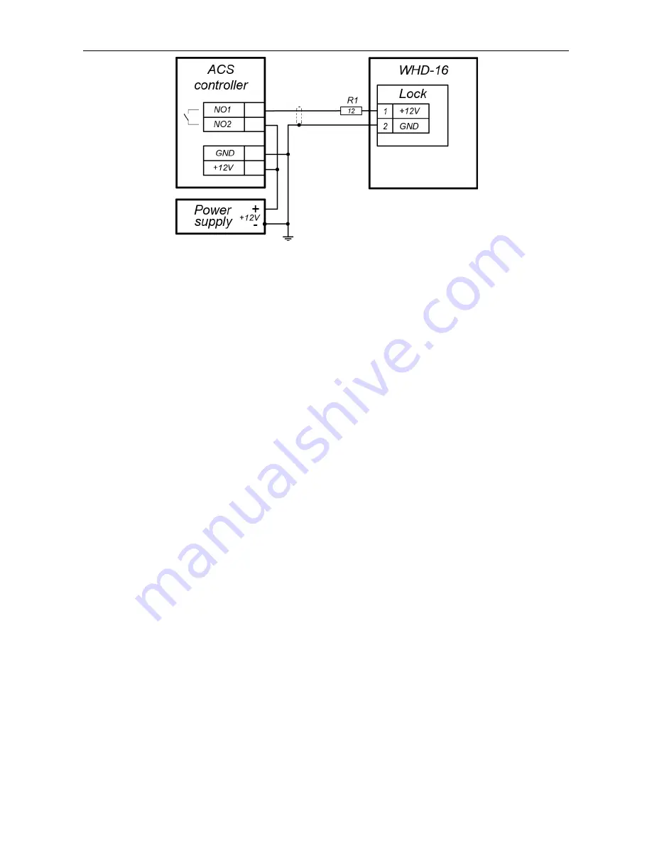
Figure 4. Recommended connection layout of the lock 

7. When  the  gate  is  operating  in  the  ACS  to  monitor  of  the  "Closed"  position  it  is 

recommended to install a door sensor (reed switch). The magnetic part of the sensor is 
installed in the leaf (it is recommended the upper part of the leaf), and the sensor itself 
is installed in the gate frame. 

8. Clear  the  passage  area  from  foreign  objects  and  check  the  operation  of  the  lock  and 

door closer according to their operational documentation. 

The gate is ready for operation. 

Summary of Contents for WHD-16

Page 1: ...INSTALLATION AND OPERATION MANUAL WHD 16 Full Height Security Gate...

Page 2: ...Full Height Security Gate WHD 16 Installation and Operation Manual...

Page 3: ...atures 8 5 2 Design and operation 8 6 MARKING AND PACKAGING 9 7 SAFETY REQUIREMENTS 9 7 1 Installation safety requirements 9 7 2 Operation safety requirements 9 8 INSTALLATION 10 8 1 General recommend...

Page 4: ...Abbreviations PS power supply ACS access control system 1 APLICATION The WHD 16 full height security gate is designed for management of pedestrian flows and access control at entrance points of facil...

Page 5: ...urrent 3 A Power consumption 36 W Throughput rate in the single passage mode 12 persons min Average daily throughput in the single passage mode 2 000 persons day Passageway dimensions H W 960 2000 mm...

Page 6: ...on request Power supply 1 MB 16 full height railing sections determined by the customer Fasteners 1 determined by the customer Anchor bolt SORMAT PFG IR 10 15 Finland 2 4 Note Technical characteristic...

Page 7: ...Installation and Operation Manual 6 Figure 1 General view of the WHD 16 gate 1 frame 2 leaf 3 electromechanical lock 4 door closer...

Page 8: ...WHD 16 Full Height Security Gate 7 Figure 2 Overall dimensions of the WHD 16 gate...

Page 9: ...through four mounting holes in the post flanges In the home position closed for entrance and exit the leaf provides complete closure of the passageway between the posts the lock is locked up After th...

Page 10: ...ed for installation Observe general electrical safety rules when laying out the cables Before the turnstile first power on make sure its installation and connection have been made accordingly Power su...

Page 11: ...00 mm for soft grounds using relevant mounting hardware for installation on different foundations making sure the mounting foundation is horizontal and flat the flatness deviation must not exceed 1 5...

Page 12: ...ble to the door sensor Fig 3 Figure 3 Mounting hole pattern 3 Insert sleeves for anchor bolts into the holes so that they do not stick out above the floor surface Attention Be extra cautious and caref...

Page 13: ...mended to install a door sensor reed switch The magnetic part of the sensor is installed in the leaf it is recommended the upper part of the leaf and the sensor itself is installed in the gate frame 8...

Page 14: ...opened with a key or remotely from the inside the lock is opened by pressing the button and remotely with the blocked exit button opening from the outside as in the normal mode and from the inside th...

Page 15: ...s high The gate should be stored indoors at ambient temperature from 40 C to 45 C and relative air humidity below 98 at 25 C The environment should be free of acid and alkali vapours or corroding gase...

Page 16: ......

Page 17: ...PERCo Polytechnicheskaya str 4 block 2 194021 Saint Petersburg Russia Tel 7 812 247 04 64 E mail export perco com support perco com www perco com...

Page 18: ...www perco com...

Reviews: