


Commissioning
2
0
1
8
-0
9
17
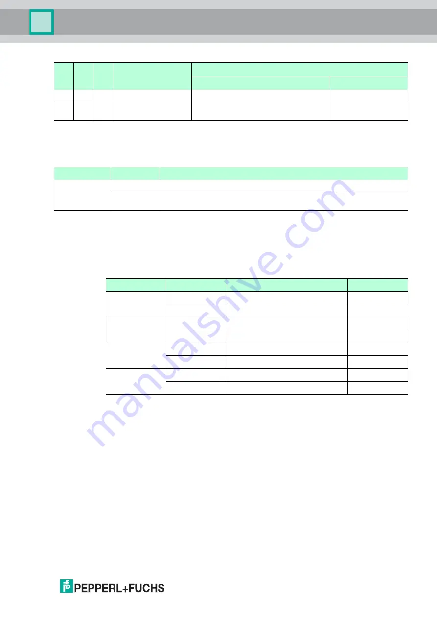
Reversing the Direction of Rotation of MOT2 (P3)
You can reverse the direction of rotation of MOT2 via parameter bit P3.
Parameter Bit P3
Status of Sensor Inputs (DI0 ... DI3)
The motor control module transfers the switch states of inputs IN1 to IN4 to the master via data
bits DI0 (IN1) to DI3 (IN4).
There is a filter upstream of the inputs that suppresses pulses
≤
2 ms.
Data Bits DI0 ... DI3
4.2
Configuring the Start/Stop Ramps
Overview
To control the acceleration and to stop the motors, you can set 1 of 8 defined start/stop ramps
for the speed signal SPEED. These ramps always apply to both motors simultaneously. The
ramp duration corresponds to the time from stopped to reaching the maximum speed or from
the maximum speed to stopped. The inclines of the ramps are constant for each of the 8 ramps
and independent of the set speed. The reference value for all ramps is the speed signal
SPEED = 9.7 V. For a lower parameterized speed, the ramp duration is proportionally shorter.
1
1
0
1
8.7 V
3.7 V
1
1
1
1
9.7 V
4.7 V
Default setting
P2
P1
P0
DO0 (MOT1)
or DO1 (MOT2)
Speed signal U
S
Fast (D3=0)
Slow (D3=1)
Parameter bit
State
Function
P3
0
counter-rotating; direction of rotation of MOT2 inverted
1
synchronized, direction of rotation of MOT1 = direction of rotation of MOT2
(Default setting)
Data bit
State
Input switching status
LEDs IN1 ... IN4
DI0
0
Unattenuated, I
IN
≤
0.5 mA
IN1: off
1
Attenuated, I
IN
≥
2.0 mA
IN1: on
DI1
0
Unattenuated, I
IN
≤
0.5 mA
IN2: off
1
Attenuated, I
IN
≥
2.0 mA
IN2: on
DI2
0
Unattenuated, I
IN
≤
0.5 mA
IN3: off
1
Attenuated, I
IN
≥
2.0 mA
IN3: on
DI3
0
Unattenuated, I
IN
≤
0.5 mA
IN4: off
1
Attenuated, I
IN
≥
2.0 mA
IN4: on