


Commissioning
2
0
1
8
-0
9
15
4
Commissioning
4.1
AS-Interface Communication
Assigning the AS-Interface Data Bits
4 data bits are available for communication between the motor control module and the master
and 4 data bits are available for controlling the motors.
The following designations apply below:
■
DI0...DI3 for AS-Interface input data (motor control module to master)
■
DO0...DO3 for AS-Interface output data (master to motor control module)
DI0...DI3 motor control module to master
DO0...DO3 Master to Motor Control Module
AS-Interface Communication Monitoring
The motor control module has a watchdog function. If there has been no communication with
the master for more than 40 ms, the motor control module sets the output data DO0...DO3 to
logical 0.
Starting/Stopping the Motors (DO0, DO1)
You can start or stop the motors separately via bits DO0 and DO1. To start the motors, you
must set the corresponding data bit to logical 1. Via the shared SPEED control signal, the
motor control module uses an analog voltage value to actuate the respective motor that has
been switched on. The SPEED control signal is released for the relevant output only when data
bit DO0 or DO1 is set. The analog voltage value corresponds to the set speed.
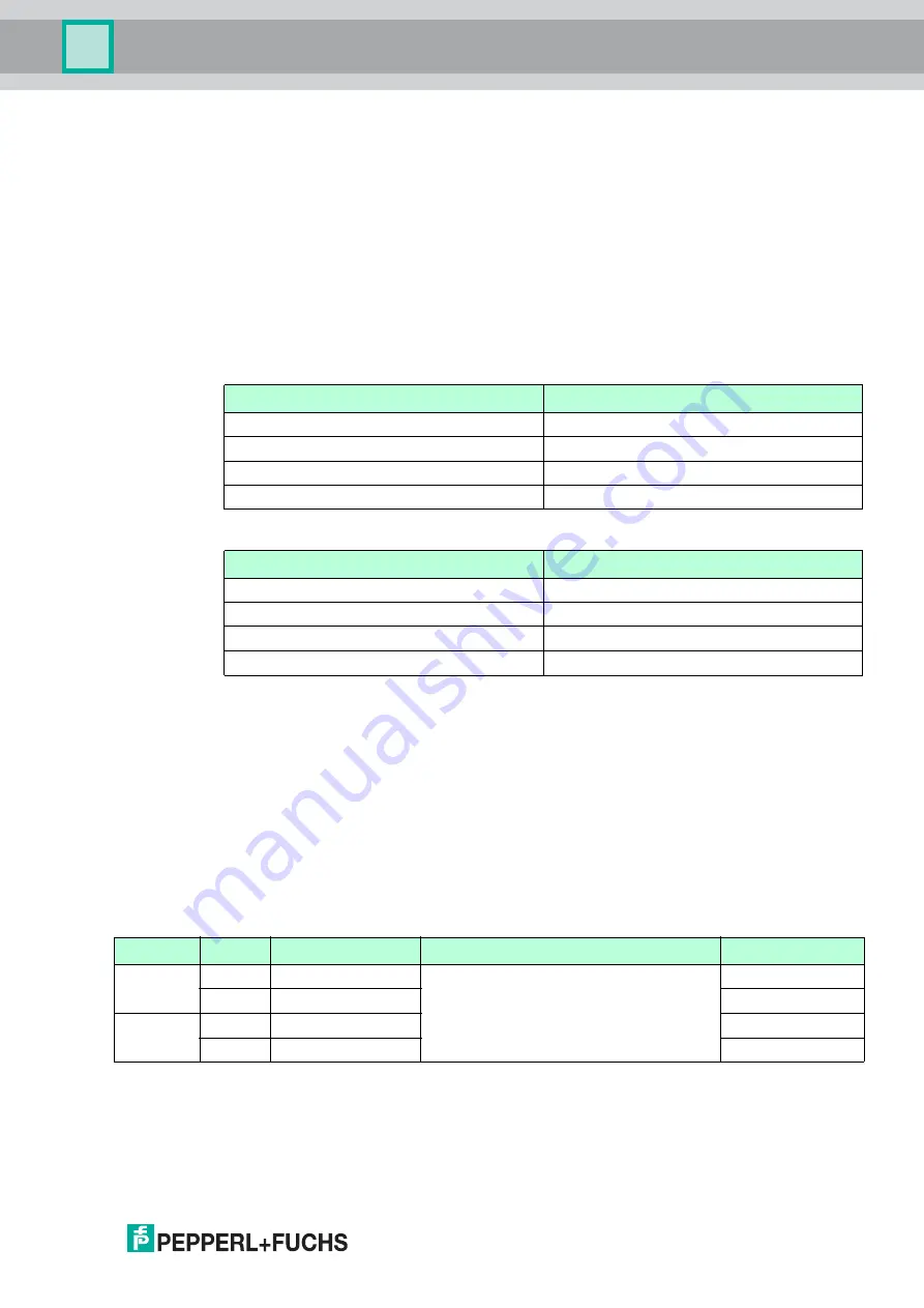
Data Bits DO0, DO1
AS-Interface data bit
Input DI
DI0
Switch state input IN1
DI1
Switch state input IN2
DI2
Switch state input IN3
DI3
Switch state input IN4
AS-Interface data bit
Output DO
DO0
Start/stop motor 1
DO1
Start/stop motor 2
DO2
Direction of rotation of motor 1 and motor 2
DO3
Slow rotation speed of motor 1 and motor 2
Data bit
State
Function
Motor start signal RUN
LED MOT1/2
DO0
1
Start motor 1
1:
≥
(U
AUX
- 2.5 V) in no-load operation
0: high impedance
MOT1: on
0
Stop motor 1
MOT1: off
DO1
1
Start motor 2
MOT2: on
0
Stop motor 2
MOT2: off