Pepperl+Fuchs UC F77 Series Manual Download Page 43

UC***-F77 series

Configuration and Analysis with DTM via IO-Link

 2

0

1

7

-0

6

43

7.8

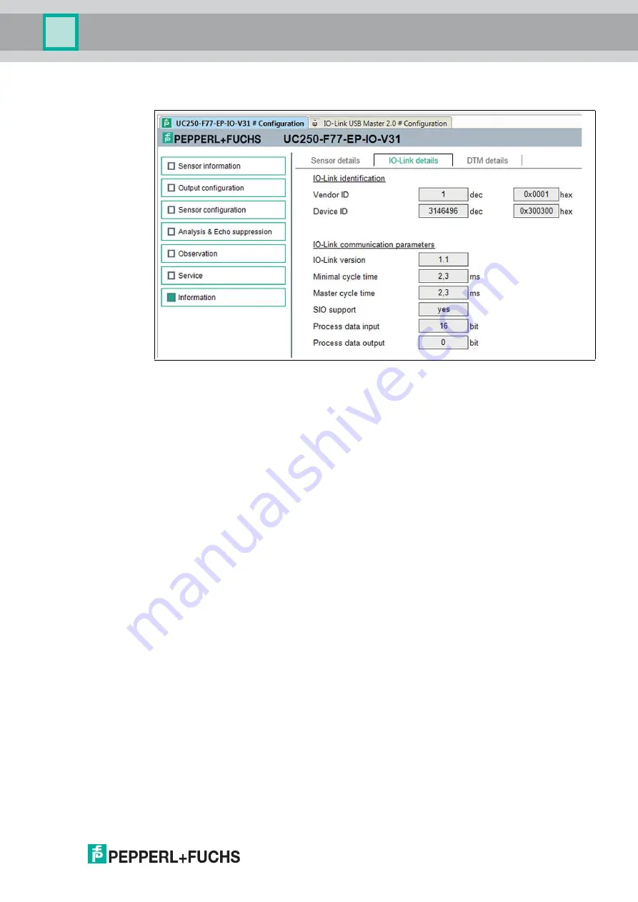
Information Menu Option

Figure 7.18

The 

Information

 menu option consists of 3 tabs

Sensor Details:

 information about hardware and software version

IO-Link Details:

 information about the device ID, vendor ID and information about the IO-

Link communication parameters

DTM Details:

 Information about the DTM version

Summary of Contents for UC F77 Series

Page 1: ...UC F77 Series Configuring Ultrasonic Sensors with IO Link Interface FACTORY AUTOMATION MANUAL...

Page 2: ...erms of Delivery for Products and Services of the Electrical Indus try published by the Central Association of the Electrical Industry Zentralverband Elektrotechnik und Elektroindustrie ZVEI e V in it...

Page 3: ...3 1 Accessories for Mounting and Connection 13 2 3 2 Configuration Aids 14 3 Installation 15 3 1 Safety Information 15 3 2 Preparation 15 3 3 Mounting 15 3 4 Connection 16 4 Commissioning without IO...

Page 4: ...Menu Option 43 8 Description of Sensor Parameters 44 8 1 Sensor Information 44 8 2 Output Switching Output 44 8 2 1 Output Mode 44 8 2 2 Output Logic 47 8 2 3 Output Type 47 8 2 4 Switch Point 1 47 8...

Page 5: ...4 13 Ultrasonic Pulse Length 59 8 5 Sensor Configuration Synchronization 60 8 6 Sensor Configuration Echo Loss and Error Handling 61 8 6 1 No Echo 61 8 6 2 Output Behavior if an Error Occurs 61 8 6 3...

Page 6: ...6 UC F77 series 12 Appendix 68 12 1 IO Link Device Parameters 68...

Page 7: ...Target Group Personnel Responsibility for planning assembly commissioning operation maintenance and dismounting lies with the plant operator Only appropriately trained and qualified personnel may carr...

Page 8: ...ity for compliance with locally valid safety regulations is borne by the operator Only use recommended original accessories 1 5 General Safety Notes Responsibility for planning assembly commissioning...

Page 9: ...ped and manufactured under observance of the applicable European standards and guidelines The product manufacturer Pepperl Fuchs GmbH D 68307 Mannheim has a certified quality assurance system that con...

Page 10: ...e irrelevant Gases cannot be detected Figure 2 1 Example of application film monitoring on a packaging machine Typically ultrasonic sensors are used in a wide range of applications including Sag contr...

Page 11: ...ult elimination maintenance and device replacement during commissioning cloning identification configuration and localization or in operation job changes continuous parameter monitoring and online dia...

Page 12: ...can be changed via IO Link On Standby high level for 1 s at synchronization input Flashing Retains previous state Off When programming the switch points Object detected Off Flashing slowly Off No obj...

Page 13: ...tting can be changed via IO Link On Standby high level for 1 s at synchronization input Flashing Retains previous state Off When programming the limits Object detected Off Flashing slowly Off No objec...

Page 14: ...erl fuchs com and the product page for the relevant UC F77 series sensor DTM for UC F77 DTM Device Type Manager device description and graphic user interface for operating the sensor integration into...

Page 15: ...unit at a later time 3 3 Mounting Mounting UC F77 sensors Use M3 cylinder head screws to secure the sensor and tighten to a maximum torque of 0 2 Nm Figure 3 1 Caution Risk of short circuit Carrying o...

Page 16: ...ly pulled out 3 Now connect the supply voltage to the cable provided for this purpose and switch it on The sensor is now ready for operation Applying supply voltage for a sensor with connection cable...

Page 17: ...hout IO Link Switch on the supply voltage The operating indicator on the sensor lights up green The sensor will now function using the preset parameters Note It is only possible to change configuratio...

Page 18: ...f the programming process the other sensors in the sensor group go into standby mode green LED is flashing Then synchronization mode continues to operate as normal 5 1 Programming Switch Points Limits...

Page 19: ...int mode 2x window mode 3x hysteresis mode 4x retroreflective mode 1 Briefly press the programming button to navigate through the output modes in succession Select the required output mode 2 Press the...

Page 20: ...ss the programming button for 5 seconds until the green LED begins to flash Programming output mode The green LED is now flashing The number of flashing pulses shows the currently programmed output mo...

Page 21: ...ng step the adjustment of the sound beam width Programming sound beam width The red LED is now flashing The number of flashing pulses displays the currently programmed sound beam width 1x small 2x med...

Page 22: ...ice Type Managers and the IODD device description for the sensor IO Link master and any required communication DTMs for upstream components are installed 2 Connect the sensor via an M8 to M12 connecti...

Page 23: ...s a window for selecting the device 4 Check IO Link USB master in the window and confirm with OK The IO Link USB master is installed as a device in the project 5 Click in the project on the IO Link US...

Page 24: ...project on the DTM 5 here as example UC250 F77 EP IO V31 The selected DTM interface is displayed 8 Click on the icon to set up the connection 6 Data connection to the sensor is established Status inf...

Page 25: ...logic In addition to configuring the sensor you can use the Analysis Echo suppression and Observation menus to display and record sensor logic in operation in order to adapt it in the best way possibl...

Page 26: ...the number of operating hours These are read only fields You can input application specific tags to identify and mark your sensor in the system environment Text information string can be input in the...

Page 27: ...ation menu option consists of 4 tabs Evaluation with reduced and advanced view Synchronization Echo loss and error handling Local controls Evaluation tab advanced view Figure 7 5 In the Evaluation tab...

Page 28: ...of the individual synchronization modes can be found in the chapter Synchronizing multiple sensors Echo loss Error handling tab Figure 7 7 In the Echo loss and error handling tab you can adjust the ev...

Page 29: ...as well as suppress the disruptive objects in the sensing area The general procedure is as follows 1 You must first establish a connection to a sensor built into the application environment 2 Ideally...

Page 30: ...suppression areas 3 Start The Start button is used to start and stop echo sampling After echo sampling has started the button changes to Stop In the case of individual echo sampling echo sampling stop...

Page 31: ...s The area allows you to manually set individual suppression areas 10 areas can be individually customized as well as deleted individually or all at once Each suppression area is determined by three p...

Page 32: ...7 11 No Name Description 1 Suppression area A rectangle indicates the specified suppression area 2 Black part of the column If multiple echo samples are shown in the graphic the black part of each col...

Page 33: ...es each fresh echo reflected from the object as its own echo and provides it accordingly These multiple echoes can be identified in the graphic as echoes in the x times actual object distance Suppress...

Page 34: ...d as Tank empty even after echo suppression In these cases a manual correction must be carried out to the corresponding suppression area to eliminate the relevant echo from the suppression see section...

Page 35: ...o comes from the object that is to be detected e g the level surface Figure 7 12 The echo to be suppressed has an amplitude of 59 at a distance of 84 mm To suppress the echo correctly and with reserve...

Page 36: ...to proper echo suppression performance With echoes from target objects which reflect well unwanted echoes in the peripheral areas can be suppressed very successfully without impairing function because...

Page 37: ...rement value in accordance with the rescale settings in the x axis and make sure it is visible in the display You can save the data displayed in this trend graphic in a file in various file formats fo...

Page 38: ...ngs parameter values will also be saved This means it is possible to evaluate recorded data later offline 3 Load data You can load the saved trend data visual observation or logging data event driven...

Page 39: ...val You can use the Interval selection function to specify the time interval at which data is recorded in the graphic There are several fixed intervals available between 100 ms and 1 hour 8 Start reco...

Page 40: ...es are available Continuous Data is continuously recorded and saved in the file Data is sequentially recorded but is not necessarily consistent Individual data may not be recorded depending on the sen...

Page 41: ...ecording is triggered Value violating defined limits Data is recorded if specified absolute limit values are exceeded The distance value in mm as well as the value at the sensor analog output if physi...

Page 42: ...activating the switch resets the sensor to settings as delivered All previous parameter changes are lost as a result of this Locator indication setting the localization display to enabled makes the LE...

Page 43: ...Option Figure 7 18 The Information menu option consists of 3 tabs Sensor Details information about hardware and software version IO Link Details information about the device ID vendor ID and informat...

Page 44: ...ng on the purpose of the sensor and its associated task you can use this parameter to individually adjust the mode for each switching output There are four options to choose from Switch point mode Win...

Page 45: ...tatus of the switching output changes if an object is detected within the area between switch points 1 and 2 The direction of motion of the object to and from the sensor is not relevant Window Mode in...

Page 46: ...round the reflector When detecting an object at a greater distance than the reference range set around the reflector the switching output changes status like when an echo does not come back to the sen...

Page 47: ...t to a farther distance than switch point 2 the two switch points are virtually inverted within the sensor This is done to ensure that the set output mode is working as intended Parameter name Access...

Page 48: ...sensing range and Beginning of adjustment range as well as values above End of adjustment range up to a certain limit Values in these ranges are outside of the adjustment range specified by Pepperl Fu...

Page 49: ...ential interference The output logic parameter determines which signal change is considered as a switch on process If the output logic is set to normally open the switch on delay effects the change of...

Page 50: ...this parameter to adapt the mode to the analog output With Rising ramp the analog output value increases with an increasing object distance with Falling ramp the analog output value reduces with an in...

Page 51: ...ensing range and Beginning of adjustment range as well as values above End of adjustment range up to a certain limit Values in these ranges are outside of the adjustment range specified by Pepperl Fuc...

Page 52: ...the small beam width via parameter or programming button Note The DTM will display just the appropriate upper output value depending on the set output type for the analog output current or voltage Par...

Page 53: ...s is to evaluate the first echo This is because the first echo corresponds to the closest object to the sensor which is relevant to the response of the sensor More rarely it can be advantageous to set...

Page 54: ...ded when determining the current distance value according to the Weighting of former measurement Allowed deviation to former measurement and Skip time parameters The evaluation produces a typical low...

Page 55: ...rmined The current measurement result is calculated arithmetically from the remaining data 8 4 5 Weighting of Former Measurement Note This parameter is only relevant and visible in the DTM if the Eval...

Page 56: ...ion of the new measurement results If the deviation is exceeded the measured values are ignored until the set skip time is reached see Skip time parameter 8 4 7 Skip Time Together with the Allowed dev...

Page 57: ...urement can be falsely influenced by external influences which heat or cool the sensor housing Such influences can be for example Solar radiation High load on the sensor output resulting in a great de...

Page 58: ...alue is set to End of dead band 8 4 11 Background Suppression You can use the Background suppression parameter to specify a range in which incoming echoes are discounted When doing so the input value...

Page 59: ...moving objects need to be detected very quickly very close to the sensor This achieves only a fraction of the nominal range because the short pulse does not provide for a large detection range It is...

Page 60: ...lel For example this could be a automatically guided transport system which is implemented with several sensors mounted in parallel With these applications it just has to be ensured that the automatic...

Page 61: ...tput in the event of an error Possible error cases are Extremely loud ambient noise in the ultrasonic frequency range of the sensor Hardware error in the sensor electronics Sensor receives no echo onl...

Page 62: ...me You can always change the sensor settings via the local controls Open This setting is only available for switching outputs It sets the output status to Open in the event of an error Replacement val...

Page 63: ...an use this parameter to switch the locator indication on and off When locator indication is activated the yellow and green LEDs on the sensor flash at the same time with a specific flashing sequence...

Page 64: ...on the driver capabilities of the external device to be used for synchronization In this case the sensors are triggered in parallel and operate synchronously i e at the same time All sensors must be...

Page 65: ...in the case of a low signal and generates an input impedance in the case of a high signal Please note that the device used for external synchronization must have the following driver capability Drive...

Page 66: ...default setting in the following ways Using the programming button Via the DTM in the Service menu Via IO Link Resetting with the programming button 1 Disconnect the sensor from the power supply 2 Pr...

Page 67: ...ector on the sensor Connect the plug to the sensor and tighten the cap nut by hand Green LED not lit up Wiring error in the splitter or switch cabinet Check the wiring carefully and repair any faults...

Page 68: ...1 enabled 0x00 Name Index dec Sub index Type Data type Value Default value Unit Process data 40 R unit16 14 bit distance value 2 bit BinaryDataChannel 1 2 Valid distance values in mm UC250 0 425 UC400...

Page 69: ...0x00 low 0x01 medium 0x02 high 0x00 Switching output Retroreflective mode offset 64 1 R W unit16 UC250 1 125 UC400 1 200 UC800 1 400 UC250 12 UC400 20 UC800 40 mm Switching output Switch off delay 64...

Page 70: ...0x00 Sensor cycle time 97 6 R W unit16 UC250 7 60000 UC400 9 60000 UC800 12 60000 UC250 7 UC400 9 UC800 12 ms Foreground suppression 97 7 R W unit16 UC250 15 250 UC400 25 400 UC800 70 1200 UC250 15 U...

Page 71: ...echo is 99 2 R W unit8 0x00 No error 0x01 Error 0x00 Switching output Behavior if error occurs 64 4 R W unit8 0 Freeze 1 Max distance 2 Closed 3 Open 1 Analog output Behavior if error occurs 114 7 R W...

Page 72: ...00 0 680 UC800 0 1200 0 mm Suppression area 3 Amplitude 98 9 R W unit8 0 100 0 Suppression area 3 Length 98 10 R W unit16 UC250 0 425 UC400 0 680 UC800 0 1200 0 mm Suppression area 4 Start point 98 11...

Page 73: ...Suppression area 9 Start point 98 26 R W unit16 UC250 0 425 UC400 0 680 UC800 0 1200 0 mm Suppression area 9 Amplitude 98 27 R W unit8 0 100 0 Suppression area 9 Length 98 28 R W unit16 UC250 0 425 U...

Page 74: ...chs GmbH 68307 Mannheim Germany Tel 49 621 776 0 E mail info de pepperl fuchs com USA Headquarters Pepperl Fuchs Inc Twinsburg Ohio 44087 USA Tel 1 330 4253555 E mail sales us pepperl fuchs com Asia P...

Reviews: