

- 18 -
PHASE, WHILE TRACING MAINS FREQUENCY,
VARY THEIR PHASES UNTIL FREQUENCY IS
COUPLED.
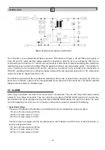
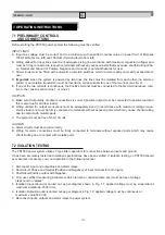
WHEN IN DOUBT ABOUT LINE ISOLATION, UTILI-
ZE AN ISOLATION TRANSFORMER 1:1 ON ONE
OF THE TWO LINES (WHICHEVER IS PREFERA-
BLE).
TRANSFORMER CHARACTERISTICS MUST BE
CHOOSEN ON THE BASIS OF REQUESTED
POWER INPUT WHICH IS ABOUT 1.4 TIMES THAT
OF POWER OUTPUT FROM POWER SUPPLY.
(i.e. OUTPUT
40A/24V = 960 WATT,
960/1.4 = 1300 VA approximately)
A SINGLE ISOLATION TRANSFORMER, IF SUITA-
BLY SIZED TO POWER, CAN BE UTILIZED FOR
MORE THAN ONE POWER SUPPLY.
IM-ENG-114/GB
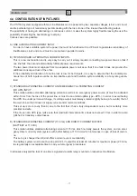
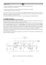
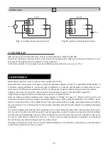
To alarm
circuit
(connection with two
normally open contacts
in parallel)
To alarm
circuit
(connection with two
normally closed contacts
in series)
LINE
MODULE #1
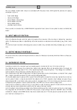
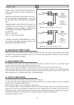
- Figure 10a - Parallel disposition of alarm contacts.
- Figure 10b - Series disposition of alarm contacts.
N o t e :
The contacts are
indicated in
de-energized state
N o t e :
The contacts are
indicated in
de-energized state
LINE
MODULE #2
LINE
MODULE #1
LINE
MODULE #2
6.2 INDICATION OF POWER FAILURE
Each line Module has a normally energized relay, which activates alarm due to lack of power supply (power failure)
via relative terminals (second example in figure 10). This permits rapid notification of malfunction and the restabili-
zation of normal operative conditions.
6.3 ALARM CONNECTIONS
For installation where alarms are actuated subsequent to opening of contacts, connect the two normally closed
contacts in series on input module (1550/TB-IN) (see Fig. 10b).
In this manner, without alarm situation, the contact remains closed and any alarm will open the series.
Otherwise if alarm utilizes for activation, contact closure, the two normally open contacts can be connected in paral-
lel so that without alarm they remain open and any alarm situation will close circuit. (see Fig. 10a). The alarm con-
tacts characteristics are: 250Vac/2Amp/100VA ; 125Vdc/2Amp/50W.
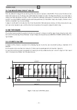
6.4 OUTPUT CONNECTIONS
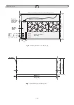
Connect the output to terminals on front panel (see Fig. 2 on Pag. 9).
For the output card model 1550/TB-OUT all 16 positive terminals are connected together via bus in analogous
manner to the 16 negative terminals (return).
Each terminal can take up to 4 Amp. Maximum wire 2.5mm2.
The 16 terminals permit a power distribution of 24V to 16 different positions within the cabinet without requiring
piggy-back connections, maintaining line voltage drop to within negligible limits. As an option the PS-1550 can be
furnished with Mod. 1550 TB-OUT 4/20 output module with 4+4 terminal block capable of handling 16 Amp each,
or with Mod. 1550 TB-OUT 60 module with 1+1 terminals that can handle up to 60 Amp each.
(See relative drawings in Fig. 2).


