
- 15 -
IM-ENG-114/GB
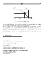
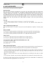
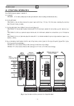
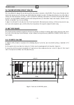
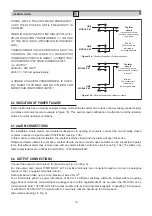
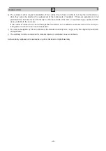
Fig. 6.
Front view of PS1550 system.
16
10
11
12
13
14
15
16
10
11
12
13
14
15
1
2
3
4
5
6
7
8
9
~
~
~
~
POWER ON
POWER ON
LM1
LM2
PM1
PM2
PM3
PM4
PM5
PM6
RET.
+
OUTPUT
24V
1
2
ON
1
2
3
4
5
6
7
8
9
483 (19")
465 (18.3")
Fans
1 2 3
Fan
Detection
OVERLOAD
OUT ON
VOLTAGE
CHECK
+
CURRENT
+
OVERLOAD
OUT ON
VOLTAGE
CHECK
+
CURRENT
+
OVERLOAD
OUT ON
VOLTAGE
CHECK
+
CURRENT
+
OVERLOAD
OUT ON
VOLTAGE
CHECK
+
CURRENT
+
OVERLOAD
OUT ON
VOLTAGE
CHECK
+
CURRENT
+
OVERLOAD
OUT ON
VOLTAGE
CHECK
+
CURRENT
+
101 (3.9")
176.6 (6.9")
A
A
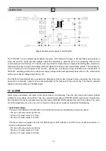
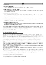
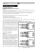
5.8 FAN MONITORING CIRCUIT BOARD
This circuit board manages the monitoring of the three fans mounted on the PS1550. Their correct function is indi-
cated when powered, by the three green LED indicators situated on panel. If voltage absorbed by one of the fans is
outside the interval between 120 mA - 420 mA (therefore indicating interruption or overload) the respective LED is
set OFF and the POWER GOOD signal lowered (stepped-down) so that alarm relays de-energize. Failure or mal-
function is signalled by a 3 second delay.
A power cut-off switch is mounted on the circuit board which interrupts power delivery to fans when panel is ope-
ned: even when panel is open, and therefore fans inoperative, the signal is relayed to alarm relay.
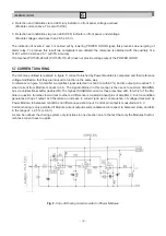
5.9 MOTHER BOARD
The mother board permits the system to function modularly: in it there are all the power buses (input current, recti-
fied current for powering Power Modules, output voltage) and signal buses (SHARING, POWER GOOD, alarm re-
lay contacts).
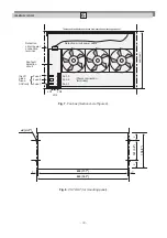
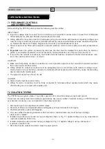
5.10 1550/RFD CHASSIS
A diagram of the chassis is reported in the following figures. As can be seen it permits housing a maximum of 10
Modules.
For the system to be mounted in a cabinet, a 19’’slot must be predisposed for its insertion (figure 6).
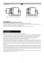
To panel mount (front panel), preparation of housing must be predisposed as per cut-out in figure 8, then insert
rack in front panel and fasten by 4 threaded screws.


