


SCREENLOGIC
®
INTERFACE Wireless Connection Kit Installation Guide
2
Antenna location
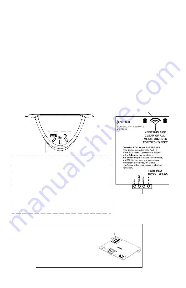
Indoor Wireless Transceiver
PWR: Green LED on: Power is on to the unit.
• PWR LED blinking: Not linked or lost link,
attempting to link or relink, no response.
• PWR LED blinking, TX and/or RX LED blinking:
not linked, attempting to link, getting responses.
• PWR LED on steady: Linked.
• PWR LED blinking: Lost link, Attempting to relink.
RX: Yellow LED indicates the unit is receiving data.
TX: Green LED indicates the unit is transmitting data.
Note: ScreenLogic Interface Indoor Wireless Transceiver (Note: For optimum
performance, mount indoor transceiver upright in the cradle or on an indoor
wall).
Summary Installation Steps
The ScreenLogic
®
Interface connection diagram on page 3 shows the
transceiver locations and connections. To install the ScreenLogic Interface
Wireless Connection kit:
RS-485 Connector
(to Protocol Adapter)
•
Mount the outdoor transceiver antenna module near the IntelliTouch
®
or EasyTouch
®
Control System Load Center (see page 4 for
mounting instructions). Using the provided 10 ft. cable, connect the
transceiver to the COM port connector located in the IntelliTouch
or
EasyTouch
Control System Load Center (see page 7).
•
Connect the ScreenLogic Interface indoor wireless transceiver to the
ScreenLogic Interface Protocol adapter using the 12 in cable. Plug
the AC power adapter into an AC wall-outlet and into the wireless
transceiver unit to power up the unit (see page 8).
ID number
(Outdoor transceiver)
IMPORTANT NOTICE: Be sure the
yellow ID label (9-digit ID number
XXXXXXXXX) located to the right of
the RS-485 connector on the front side
of the Indoor transceiver
enclosure and the ID number
on the ScreenLogic Interface Outdoor
Wireless transceiver are the same. See
page 1 for label location.
LED Indicators Description:


