Pentair SCREENLOGIC INTERFACE Installation Manual Download Page 10

SCREENLOGIC

® 

INTERFACE Wireless Connection Kit Installation Guide

8

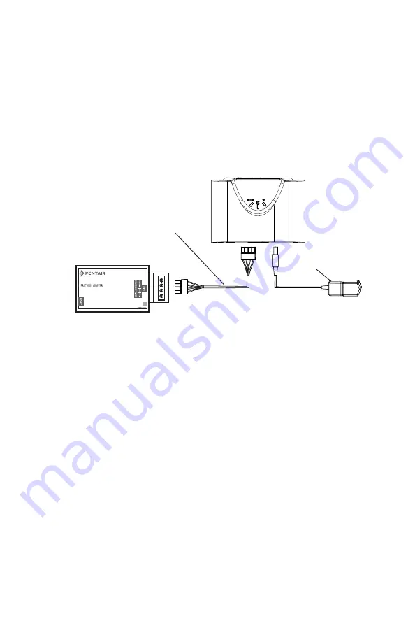
Connecting the Indoor Wireless Transceiver and Protocol Adapter

Connect the Indoor Wireless Transceiver to the ScreenLogic

®

Interface Protocol Adapter

Connect the ScreenLogic Interface indoor wireless transceiver to the
ScreenLogic Interface Protocol adapter as follow:

1.

Using the 1 ft. connection cable, connect one end of the cable to the
Protocol Sdapter and the other end to the Indoor Wireless
Transceiver. See Figure 1 and Figure 2. The cable plugs are keyed for
easy connection.

2.

Plug the 120 VAC Power Adapter into an AC grounded electrical
outlet.

Wall Mount the Indoor Wireless Transceiver (Figure 2 and Figure 3)

1.

Cut out the wall mounting templating from the next page. Place the template
on an indoor flat surface or wall and mark the two screw hole positions.

2.

Drill two holes (0.223 in) 2-1/2 inches apart as shown on the template (see
Figure 3 on next page).

3.

Insert the wall plugs into both wall screw holes.

4.

Insert the screws into the wall plug. Don’t insert the screws all the way into
the wall, leave about 1/16 in for the wireless transceiver to hang on the head
of the screws (see Figure 2 on next page).

5.

Mount the wireless transceiver onto both screw heads.

Cradle/Desk Mount the Indoor Wireless Module (Figure 1)

1.

Insert the power cable into the base of the Indoor transceiver cradle. Fasten
the cable into the cradle slot (see Figure 1 on next page).

2.

Insert the connection cable into the base of the Indoor transceiver cradle.
Fasten the cable into the cradle slot (see Figure 1 on next page).

3.

Place the cradle on a table or desk.  Note: Keep the cradle and Indoor
transceiver clear of all objects for two feet.

Mount the Indoor Wireless Transceiver in its cradle as follows:

Mount the Indoor Wireless Transceiver on an indoor wall as follows:

SCREENLOGIC   INTERFACE

®

Connection cable (1 ft)

(provided in kit)

120 VAC
Power Adapter

Indoor Wireless Transceiver

Protocol Adapter

Summary of Contents for SCREENLOGIC INTERFACE

Page 1: ...onnection Kit Installation Guide IMPORTANT SAFETY INSTRUCTIONS READ AND FOLLOW ALL INSTRUCTIONS SAVE THESE INSTRUCTIONS INSTALLATION GUIDE SCREENLOGIC INTERFACE WIRELESS CONNECTION KIT FOR INTELLITOUC...

Page 2: ...ned by turning the equipment off and on the user is encouraged to try to correct the interference by one or more of the following measures Reorient or relocate the receiving antenna Increase the separ...

Page 3: ...X Outdoor Transceiver enclosure Indoor transceiver and base AC transformer Outdoor Cable white 10 ft NOTE ID numbers on Indoor and Outdoor transceiver board must match Indoor hardware Cable for connec...

Page 4: ...all the ScreenLogic Interface Wireless Connection kit RS 485 Connector to Protocol Adapter Mount the outdoor transceiver antenna module near the IntelliTouch or EasyTouch Control System Load Center se...

Page 5: ...RJ45 CAT 5 DSL or Cable Modem RJ45 Cable distance limits Ethernet cable distance limit 300 feet Four wire cable distance limit 1500 feet Note Optional wiring for existing Indoor Control Panel Tap into...

Page 6: ...ting surface so that the transceiver is oriented in an upright position with the antenna pointing upwards Use a pencil to mark the four mounting points Drill four 3 16 in diameter holes into the mount...

Page 7: ...r mounting circuit board Outdoor wireless transceiver circuit board Connect 4 conductor communication cable to terminal screws Outdoor Transceiver connector COM PORT RS 485 screw terminal connector on...

Page 8: ...nel to access the circuit board sockets connectors for the electrical connections Remove the panel from the enclosure see illustration below 4 Route the four conductor transceiver connection cable int...

Page 9: ...connection Note For additional COM ports an optional Serial COM Port Expansion Board P N 520818 can be installed in the low voltage compartment 6 After the communication cable connection has been comp...

Page 10: ...hes apart as shown on the template see Figure 3 on next page 3 Insert the wall plugs into both wall screw holes 4 Insert the screws into the wall plug Don t insert the screws all the way into the wall...

Page 11: ...e Mounting Screw Location Figure 2 Wall Mount the Indoor WirelessTransceiver Figure 1 Cradle Desk Mount the Indoor Wireless Transceiver Hang module on screw head approx 1 16 in from wall surface 1 16...

Page 12: ...ies iPhone is a registered trademark of Apple Corporation Unless expressly noted names and brands of third parties that may be used in this document are not used to indicate an affiliation or endorsem...

Reviews: