


7
than 500,000 ohms after
drying. A hypot check of 1,500
volts for 230 volt motors and
2,000 volts for 460 volt motors
should be performed.
2. Remove cutters, impeller and
pump parts as described under
“Re plac ing Grinder Parts”.
3. Remove socket head cap screw
(25) in seal plate (17) and
screw two of the screws into
the tapped back-off holes to
force seal plate (17) from seal
housing (27). Pull ing this plate
(17) off will also force seal
(23) from shaft. Re move lower
seal (23) from seal plate (17).
4. Remove snap ring (26) and
pull up per seal (28) from shaft.
It may be necessary to use
packing hooks to remove seal.
Use a screwdriver to break the
upper stationary ce ram ic seal
ring so that it can be removed
easily.
CAUTION: Do not use any old
seal parts. Replace all parts
with new pieces. Mixing old and
new parts will cause immediate
seal failure.
5. When cleaning all parts before
re place ment, check to be sure
sleeve bearing or shaft is not
worn. Be sure all O-rings are in
excellent condition without
cuts or nicks, and replace them
if not i n ex cel lent condition.
Use O-ring lube to prevent
cutting at assembly.
6. After upper seal is replaced we
rec om mend an air test be made
by inserting 5 lb. of air pressure
into the motor hous
ing and
allow am
ple time for air to
escape. If pressure remains
Pump
Maintenance
steady for five minutes
continue by replacing low
er
seal plate, lower shaft seal and
impeller. Repeat the air test in
the seal chamber. If this test
is satisfactory, complete the
assem bly and cutter adjustment
as de
scribed earlier. Next the
pump must be filled with oil.
Start by filling the seal
chamber. Do not fill it
completely. Allow about 1/2"
air space for expansion. Next
fill the motor housing just
above the motor winding.
7. Use only Hydromatic
sub
mers
ible oil in motor
chamber and seal chamber. In
an emergency, a high grade
trans
form
er oil can be used
in the motor chamber and #20
non-detergent automobile oil
can be used in the seal chamber.
Replacing Motor Stator:
1. If necessary to replace stator,
com plete ly dismantle pump as
de scribed above.
2. Drain all oil from upper housing.
Remove drain plug (12) in
bottom of bearing housing, and
remove bearing housing (8)
and rotor and shaft assembly
(33). When hous ing and rotor
are removed, motor leads can
be disconnected through
the bearing cap bore. The
leads are connected with
connectors and must be cut.
DO NOT TAPE LEADS
WHEN REPLACING STATOR
AS OIL WILL DE TE RI O RATE
THE TAPE AND CAUSE
MOTOR FAILURE. USE
ONLY INSULATED BUTT
CONNECTORS.
3. If cord leads are burned, it will
be necessary to replace power
cord and cord group assembly
(1). If any wires in the
connection box (41) are
burned, it will be nec es sary to
replace the connection box
assembly. Connect wires per
con nec tion diagram.
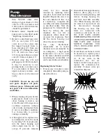
16
25
17
26
64
48
31
46
49
50
51
53
15
18
14
30
29
7
45
32
45
35
8
52
54
24
23
28
13
27
11
10
6
5
3
2
1
47
42
4
34
9
12
59
19
58 57 56 22
21 20 55
41 40 64 38 39
33
43
44
;;;;
;;;
;
;
;;;
;;;
;;;
;
;
;
;
;
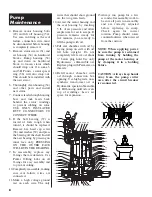
40
39
38
8
63
62
53
52
64
65
37
67
50
49
66
51


