


Making Electrical Connections
All electrical wiring must be in
ac
cor
dance with local code, and
only qual i fied electricians should
make the in stal la tions. Complete
wiring di a grams are included for
use in making the installation.
All wires should be checked for
shorts to ground with an
ohmmeter or Megger after the
con
nec
tions are made. This is
important, as one grounded wire
can cause con sid er able trouble.
I
MPORTANT: If equipment
is not properly wired and
protected as recommended,
Hydromatic WAR RAN TY IS
VOID.
Heat Sensor and Seal Failure
Connection
If a Hydromatic control panel
is used, terminal blocks are
provided for heat sensor and seal
failure con
nec
tions (see Panel
Schematic). If a con trol panel is
supplied by others, it must allow
heat sensor and seal fail
ure
terminations.
Installing Sump Level Control
Float Controls
In either simplex, duplex or
triplex systems the lower or turn-
off control is to be set to maintain
a minimum level in the sump.
This level shall be no more than
3-1⁄2" from the top of the motor
housing down to the surface of the
sew age.
The second, or turn-on control, is
set above the lower turn-off
control. The exact distance
between the two floats must be a
compromise between a fre
quent
pumping cycle (10 starts per hour
maximum) to control septicity,
solids and a slower cycle for
energy economy. This distance
should be de
ter
mined by the
engineer or con sult ing engineer,
Starting the Pump
To start the pump, per
form the
fol low ing steps in order:
WARNING! Keep hands and
cloth ing away from cut ters and
im pel ler!
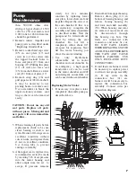
1. If pump is 3 phase, the rotation
of the impeller must first be
checked. Lift pump from
sump, lay it down, and quick ly
turn pump on and then off.
The impeller should turn
coun ter clock wise
when
viewed from the suc
tion. If
rotation is wrong, turn off main
breaker and interchange any
two line leads to motor to
correct rotation.
If the pump is piped-in
permanently and inlet cannot
be observed, ro ta tion will have
to be checked by pump
operation de scribed later.
If pump is single phase, no
ro ta tion check is necessary.
2. Run water into sump until
motor is covered.
3. Open gate valve in discharge
line.
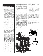
4. Turn pump on. If pump runs and
sump liquid does not pump
down, stop pump and close
discharge gate valve. Then lift
pump until sealing flange is open
to vent off trapped air. Lower
pump, open discharge valve, and
start the pump again.
If the pump is piped
in permanently, it may be
Unpacking Pump
Remove pump from carton.
Remove plywood base from
bottom of pumps.
Installing Pump in Sump
Before installing pump in sump,
lay it on its side and rotate
impeller. Im pel ler may be slightly
stuck due to fac to ry test water so
it must be broken loose with a
small bar or screwdriver in edge
of vanes. The impeller should turn
free ly. Do not connect the power
until after this test.
Clean all trash and sticks from
sump and connect pump to piping.
A check valve must be installed
on each pump.
Location
If pumps are installed in an
existing basin or concrete sump,
the piping can either be connected
permanently or rails and brackets
can be furnished for mounting to
walls of basin. In either case, be
sure the Hydromatic non-clog
ball check valve is used and that
the pumps are submerged in a
vertical position. The complete
fac to ry built packaged sys tem is
recommend
ed for the most
satisfactory
in stal la tion
and
generally for the low
est cost
where expensive in stal la tion labor
is involved.
Pump
Installation
Pump
Operations
3
generally for the low
est cost
where expensive in stal la tion labor
is involved.
de pend ing on the con di tions of
the application.
For installation of Hydromatic
sup
plied level controls refer to
your sys
tems installation and
service manual.


