


5
As the motors are oil filled, no
lubri
ca
tion or other maintenance
is required.
If the heat sensor and seal failure
are hooked up properly, no
attention is necessary as long as
the seal failure indicator light
doesn’t come on. To ensure
continuity of the seal sensor
leads, a test light is provided on
in trin si cal ly
safe
Hydromatic
pan els as standard equip ment.
Pump should be checked every
quar ter for cor ro sion and wear.
Servicing Instructions:
I
MPORTANT: Read all the
in struc tions before replacing
any parts.
WARNING: Before handling
these pumps and controls,
always dis
con
nect the power
first.
Do not smoke or use sparkable
elec tri cal devices or flames in a
septic (gaseous) or possible
septic sump.
Field Service on Hydromatic
Explosion-Proof Pumps:
If a Hydromatic explosion-proof
pump is used in a hazardous
location, or if the pump is still in
warranty, the pump must be
returned to the factory for service
or repaired in an au
tho
rized
Hydromatic service center. This
will ensure the integrity of the
hazardous location rating of the
pump and comply with our
warranty re quire ments. Pumps
out of warranty and not used in a
hazardous location can be field
serviced by any reputable
service
man. When any field
servicing is performed on a pump,
the fol low ing instructions should
be fol lowed carefully.
Disconnecting Pump Cords:
If a Hydromatic explosion-proof
pump is to be removed from its
loca tion, one of two ways may be
used to disconnect the pump cords
from the rest of the system.
Pump cords may be disconnected
at control panel (on sump mounted
con trol panels) and cord assembly
taken with pump.
CAUTION: If cord openings
from sump to control panel are
open, gas
es from sump could
enter panel and an explosive
condition could exist. Seal
openings!
Pump cords may be disconnected
at pump by removing the cord and
cap assembly, un plug ging sensor
wires, and removing wire nuts.
After removal from pump, reinstall
wire nuts in cord and cap assembly
and install protective cover.
(Required accessory item when
re mote mounted control panel is
used PN #11159-000-1.)
Pump
Maintenance
CAUTION: Do not reconnect
pow er to a cord and cap assembly
while removed from pump.
Replacing Cords:
The power cord and heat
sensor/seal failure cord are potted
into the con
nec
tion box cap,
form ing the cord and cap assembly.
If cords require replacement due
to damage or cords being too
short, cord and cap assembly must
be replaced as a complete assembly
available from factory.
1. Remove cord and cap assembly.
2. Disconnect wires taking note
of col or/number coding.
3. Connect wires of new cord and
cap assembly in same manner
as old one was removed.
4. Reinstall cord and cap assembly
taking care not to pinch wires.
5.
Check pump for proper
rotation before returning to
normal service.
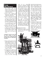
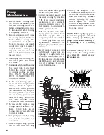
Axial Cutter Adjustment:
To maintain the proper face
clearance between the axial cutter
(57) and the cutter ring (58),
follow this procedure.
1. Close gate valve at pump
discharge.
2. Turn off circuit breaker.
CAUTION: Never work on
pump unless power has been
turned off.
3. Remove pump from sump.
4. Referring to drawing, loosen
jam nuts (52) on set screws
(53) lo cat ed on top of bearing
housing (8).
5. Loosen set screws (53).
6. Tighten hex head cap screws
(40) until axial cutter (57) just
drags on cutter ring (58) when
radial cutter (56) is turned by
hand.
necessary to break union at
pump discharge to clear air.
5. If pump is 3 phase, piped-in
per ma nent ly, and still does not
op er ate properly after venting,
rotation is wrong and can be
reversed by in ter chang ing any
two line leads.
6. Level controls should be set in
ac cor dance with “Installing
Sump Level Control Float
Controls” above.
CAUTION: Be sure ground
wire is connected to good
ground such as a water pipe.
This is important for safe ty.


