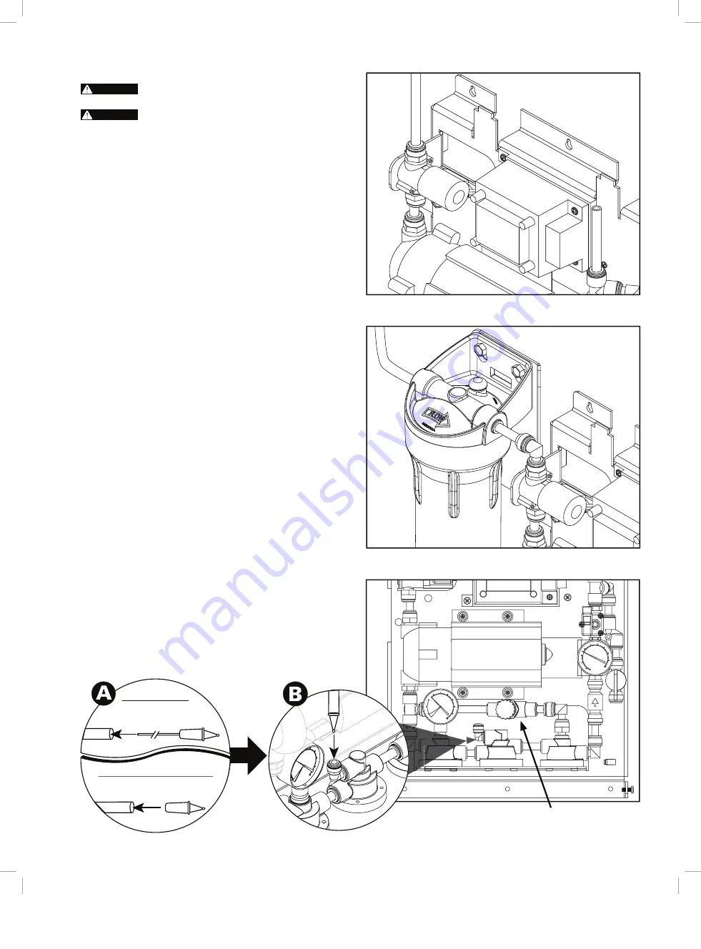
figure 4.
Pre-filter
figure 3.
No Prefilter
figure 5.
RO Reject Flow Control Assembly
3
6. Attach processor to the vertical surface with screws and
anchors designed for the mounting surface material.
WARNING
Do not use screws smaller than #12 for mounting the
processor.
WARNING
Mounting surface may require reinforcement to
support processor safely. Hollow walls, drywall and other non-
structural surfaces are not suitable unless reinforced.
Piping/tubing connections
Refer to Figure 2 for views of the piping, with a description of major
1.
components and connection points. These major components and
connections will be referred to in the following steps.
Prepare the plumbing to accept the RO system. It is recommended
2.
that a three valve by-pass is installed to provide an uninterrupted
supply of water when the RO system requires service.
note:
The product water tubing/piping and associated fittings
connecting the RO product outlet to the equipment being serviced
should be food grade material that meets NSF Standard 51 or 61
with a minimum pressure rating of 75-PSI. The product water
will react with most metal piping, creating a corrosive condition,
in addition to imparting an objectionable taste. Plastic pipe or
reinforced tubing are generally very good choices for RO water
distribution materials. The size of the product water tubing/piping
should be 3/8" ID minimum. Distances of 25 feet or greater from
the RO to the equipment being serviced should be 1/2" ID minimum.
Connect the inlet supply.
3.
MODELS WITHOUT PRE-FILTER – See Figure 3. Connect to
A.
the Inlet open port (3/8" JG) on the solenoid valve.
MODELS WITH PRE-FILTER – See Figure 4. Connect to the
B.
Inlet open port (3/8" JG) on the pre-filter head.
Connect the appropriate size and type of tubing/piping and
4.
associated fittings to the outlet tee connection. Route the line(s)
to the equipment being serviced (i.e.; espresso, coffee, etc.).
Locate the storage tank directly below or adjacent to the
5.
processor assembly. Be sure the mounting surface is capable
of supporting the weight of the tank when full (see specification
table for operating weights). Install an isolation valve and drain
valve at the storage tank, then connect a suitable length of 3/8"
OD tubing to the tank isoaltaion valve. Rote this section of tubing
to the main processor assembly. Connect the tubing to the elbow
fitting or open Y-connector port attached to the right-side of the
processor.
note:
The storage tank pre-charge pressure should be
checked and adjusted when the storage tank is empty. For
most applications, a low (5-10 psi) pre-charge pressure is
recommended, to attain maximum storage tank volume.
Close the inlet, outlet and by-pass valves.
6.
Locate the correct reject flow control assembly based on the
7.
illustration below (A). Insert the reject flow control assembly
into the 1/4
"
OD tube (See A below). Insert the 1/4
"
OD tube
with reject flow control assembly into the elbow fitting on RO
head (See B below). Route the other end of the tubing to a drain
nearby, securing it temporarily. Allow an air gap at the drain,
following any applicable local codes. See Figure 5.
continued on the next page . . .
TUBE
FLOW
CONTROL
Model MRS-100
TUBE
FLOW
CONTROL
Model MRS-225 & MRS-350
blend Valve
(BL model only)
3123-42b IO Guide MRS - 112108.indd 3
9/11/09 11:15:29 AM


