background image

5


E-03-558 (07-05-20)

INSTALLING PUMP IN SUMP

Before installing the pump in the sump, lay it on its side and rotate 
impeller. Impeller may be slightly stuck due to factory test water. 
The impeller should turn freely. 

DO NOT

 connect the power until 

after this test.

Clean all debris from sump and connect pump to piping. A check 
valve must be installed on each pump and a gate or plug valve 
in each pump discharge is highly recommended. This valve 
should be installed on the discharge side of the check valve so 
if it becomes necessary to service the check valve, the line 
pressure can be cut off. Single pump systems are sometimes 
installed without a check valve where it is desirable to self-drain 
the discharge line to prevent freezing. This can be done only with 
short discharge lines; otherwise water will return to the sump and 
cause short cycling of the pump.

MAKING ELECTRICAL CONNECTIONS

All electrical wiring must be in accordance with local codes, 
and only competent electricians should make the installations. 
Complete wiring diagrams are glued to the inside cover of the 
panel. It is VERY IMPORTANT to check all wires for grounds with 
an ohmmeter or Megger(r) after the connections are made 

as 

one grounded wire can cause considerable trouble

.

IMPORTANT:

 If equipment is not properly wired and protected as 

recommended, the warranty is void.

 The 230 volt 3 phase pump has a dual marked 

nameplate. For ordinary location pumps, voltage may be rewired 
by qualified personnel. For hazardous location pumps, voltage 
may be rewired by the manufacturer or a Class I, Div I equipment 
qualified electrician. Once the voltage is changed, the factory 
cord tag indicating 230 volt 3 phase must be removed.

For record keeping purposes, we suggest the pump be marked 
externally with the new voltage and qualified personnel that 
performed the change. Pumps shipped from the factory as 460 
volt 3 phase cannot be rewired to any other voltage.

TO RE-WIRE THE PUMP FROM 230V TO 460V 3 PHASE

Only a 230V pump from the factory is considered dual voltage, a 
cord label clearly states the factory wound voltage.
 
1.  Remove all six (#7) cap screws then raise the cord cap 

assembly enough to slip a prying instrument on opposite 
sides between the cord cap casting and the motor housing. 
Take care to not damage the o-ring or the machined 
surfaces of the castings. Doing so could void FM agency 
certifications. 

2.  While prying evenly on both sides; separate the cord cap 

casting from the motor housing, the assembly is airtight 
and will have a vacuum effect when disassembling.

3.  Once separated, the cord cap can be inverted and rotated 

to the outside of the pump assembly, and a bolt can be 
re-used to secure the upside down cord cap to the motor 
housing for ease of rewiring. 

Refer to the wiring diagram within this manual for wiring 
details. Once all electrical connections are finished and secure 
(a crimped electrical connector is best to prevent issues due 
to vibration if required), the cord cap should be re-attached 
reversing the steps above.  Ensure the o-ring is in place and 
perform a hi-pot test for safety once everything is complete.

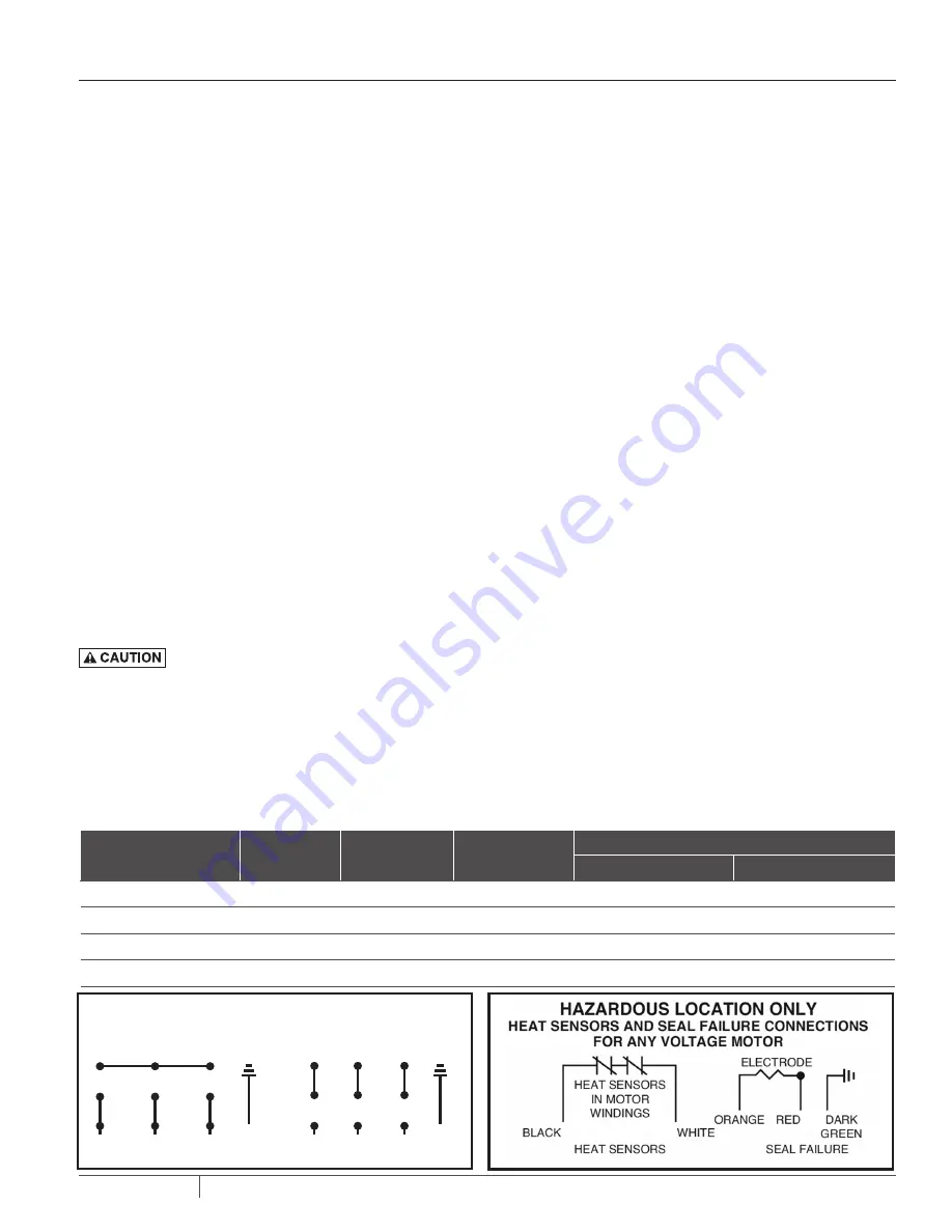
HEAT SENSORS AND SEAL FAILURE CONNECTIONS

Be sure heat sensor wires are connected in series with the starter 
coil. Connections are provided on the terminal strip.

PUMP INSTALLATION

System Type

Number of 

Control Wire

Number of 

Power Line

Number of 

Ground Wires #8

Heat Sensor & Seal Failure

Number of Sensor Wires

Number of Ground Wires

Simplex

4

3

1

3

1

Simplex with Alarm

6

3

1

3

1

Duplex

6

6

2

6

2

Duplex with Alarm

8

6

2

6

2

NUMBER OF CONDUCTORS REQUIRED BETWEEN CONTROL PANEL AND NEMA 4 JUNCTION BOX

Power lines and control wires can be carried in conduit or can be underground buried cable

DUAL VOLTAGE

3 PHASE MOTOR WIRING

230V  3ø

460V  3ø

GREEN

GREEN

R

(L3)

W

(L2)

BL

(L1)

R

(L3)

W

(L2)

BL

(L1)

1

2

3

7

8

9

4

5

6

1

2

3

7

8

9

4

5

6

ELECTRODE RESISTANCE 330 

Summary of Contents for C4H(X)P

Page 1: ...t 056255581 2020 All Rights Reserved INSTALLATIONAND OPERATIONMANUAL SUBMERSIBLE SOLIDSHANDLING PUMP C4H X P H4Q X P S4K X P S4L X P S4LV X P S4B X P S6L X P S6A X P S8F X P Used in hazardous locations Class I Division I Groups C D FM ...

Page 2: ...TABLEOFCONTENTS SECTION PAGE Safety Information 3 General Information 4 Pump Installation 5 Pump Operation Maintenance 6 Troubleshooting 7 Parts List 8 Wiring Diagrams 15 Warranty 16 ...

Page 3: ...ial An improperly sized tank can cause the pump to cycle and lead to pump damage This may require a larger pressure tank than is normally used CALIFORNIA PROPOSITION 65 WARNING This product and related accessories contain chemicals known to the State of California to cause cancer birth defects or other reproductive harm ELECTRICAL SAFETY ELECTROCUTION HAZARD Must be installed by a qualified profes...

Page 4: ...inding temperature the starter in the panel breaks power to the pump Once the sensor resets the starter is automatically reset for FM for continued operation of the pump This circuitry is supplied in a Hydromatic control panel The sensors are set to trip at 130 C Failure to install such circuitry would negate FM approvals and all warranties by Hydromatic POWER CORDS The power cord and heat sensor ...

Page 5: ...nge Pumps shipped from the factory as 460 volt 3 phase cannot be rewired to any other voltage TO RE WIRE THE PUMP FROM 230V TO 460V 3 PHASE Only a 230V pump from the factory is considered dual voltage a cord label clearly states the factory wound voltage 1 Remove all six 7 cap screws then raise the cord cap assembly enough to slip a prying instrument on opposite sides between the cord cap casting ...

Page 6: ...ble motors that are out of warranty can be serviced in the field by any reliable motor service shop Any pump that is in warranty must be returned to the factory for service or repaired at an authorized Pentair Hydromatic service center Charges will not be allowed if in warranty pump is not taken to an authorized Pentair Hydromatic service center When field service is performed on a pump these inst...

Page 7: ...city 1 Discharge gate valve may be partially closed or partially clogged 2 Check valve may be partially clogged Raise level up and down to clear 3 Pump may be running in wrong direction Low speed pumps can operate in reverse direction without much noise or vibration 4 Discharge head may be too high Check total head with gauge when pump is operating Total head is discharge gauge pressure converted ...

Page 8: ...5 CORD CAP ASSEMBLY 4 4 W 1 25 107550312 SEAL PLATE 1 132531001 OIL DIELECTRIC VARIES PUMP PARTS LIST 1 2 3 4 5 7 8 12 11 15 16 18 19 10 A1 A2 A4 24 6 16 16 17 13 14 20 21 A3 22 23 9 20 25 250 FRAME PUMPS Ref Part No Part Description Qty 1 28012D000 MOTOR HOUSING 1 2 27966D010 BEARING HOUSING 1 3 27882A009 TERMINAL BLOCK 1 4 06106A069 SCREW CAP SKT HD 2 5 110650043 SCREEN 1 6 19331A009 WASHER SPRI...

Page 9: ...1 005700181 005700181 005680191 D7 SCREW MACHINE NOT SHOWN SEE VOLUTE ASSY 008290061 3 008290061 3 N A SEE VOLUTE ASSY SEE VOLUTE ASSY 008290091 4 SEE VOLUTE ASSY N A D8 WEAR RING SEE VOLUTE ASSY 136900003 136900003 N A SEE VOLUTE ASSY SEE VOLUTE ASSY 136900003 SEE VOLUTE ASSY N A D9 CUTTER PLATE N A N A N A N A N A N A N A N A 153600002 D10 CUTTER INSERT N A N A N A N A N A N A N A N A 153320014 ...

Page 10: ...A027 A4 SPACER 076650041 076650041 076650041 076650121 076650121 076650121 CONNECTOR 12672A001 12672A001 ITEM 8 POLE 870 RPM 10 15 HP 10 15 HP 10 15 HP 208 230 3 60 460 3 60 575 3 60 A1 STATOR 27963D003 27963D003 27963D603 A2 ROTOR SHAFT ASSEMBLY 27963D011 27963D011 27963D011 A3 BOLT STATOR 4 005560081 005560081 005560081 A4 SPACER 076651001 076651001 076651001 CONNECTOR 12672A001 ITEM 6 POLE 1150...

Page 11: ...8 110430382 S4LV X P4000FC 40 460 3 6 4 11 5 110430012 S4LV X P4000GC 40 575 3 8 4 11 5 110430012 1150 RPM S4LV X P750DB 7 5 208 3 8 4 10 110430042 S4LV X P750EB 7 5 230 3 8 4 10 110430042 S4LV X P750FB 7 5 460 3 10 4 10 110430042 S4LV X P750GB 7 5 575 3 10 4 10 110430042 S4LV X P1000DB 10 208 3 8 4 11 25 110430082 S4LV X P1000EB 10 230 3 8 4 11 25 110430082 S4LV X P1000FB 10 460 3 10 4 11 25 1104...

Page 12: ...025940002 S4L X P750FA 7 5 460 3 10 4 11 88 025940002 S4L X P750GA 7 5 575 3 10 4 11 88 025940002 S6L X P Cat No HP Volt Ph Cord Trim Impeller 1750 RPM S6L X P2000DC 20 208 3 6 4 9 88 025940372 S6L X P2000EC 20 230 3 6 4 9 88 025940372 S6L X P2000FC 20 460 3 8 4 9 88 025940372 S6L X P2000GC 20 575 3 8 4 9 88 025940372 S6L X P2500DC 25 208 3 4 4 10 25 025940072 S6L X P2500EC 25 230 3 6 4 10 25 0259...

Page 13: ... P2500FC 25 460 3 8 4 10 13 025940172 S8F X P2500GC 25 575 3 8 4 10 13 025940172 S8F X P3000EC 30 230 3 4 4 10 5 025940082 S8F X P3000FC 30 460 3 8 4 10 5 025940082 S8F X P3000GC 30 575 3 8 4 10 5 025940082 S8F X P4000FC 40 460 3 6 4 11 38 025940202 S8F X P4000GC 40 575 3 8 4 11 38 025940202 1150 RPM S8F X P750DB 7 5 208 3 8 4 10 38 025940162 S8F X P750EB 7 5 230 3 8 4 10 38 025940162 S8F X P750FB...

Page 14: ...20 460 3 8 4 12 136920012 S4B X P2000GB 20 575 3 10 4 12 136920012 870 RPM S4B X P1000DA 10 208 3 8 4 12 136920012 S4B X P1000EA 10 230 3 8 4 12 136920012 S4B X P1000FA 10 460 3 10 4 12 136920012 S4B X P1000GA 10 575 3 10 4 12 136920012 S4LV X P CAT NO HP VOLT PH CORD TRIM IMPELLER 1750 RPM S4LV X P5000FC 50 460 3 4 4 12 110430002 S4LV X P5000GC 50 575 3 6 4 12 110430002 S6A X P CAT NO HP VOLT PH ...

Page 15: ...15 E 03 558 07 05 20 WIRINGDIAGRAMS ...

Page 16: ...ll dual seal pumps Under no circumstance will Pentair Hydromatic be responsible for the cost of field labor travel expenses rented equipment removal reinstallation costs or freight expenses to and from the factory or an authorized Pentair Hydromatic service facility This limited warranty will not apply a to defects or malfunctions resulting from failure to properly install operate or main tain the...

Reviews: