background image

MANUAL SGM800 


34 


CAL code (Calibration counter). 

The SGM800 has a CAL code inside. CAL code is the number of times the calibration is 
changed. When an indicator gets certified this number will be written on the device and 
is used by the controlling agency to see if the settings are

n’t changed after sealing.


To check out the 

CAL code 

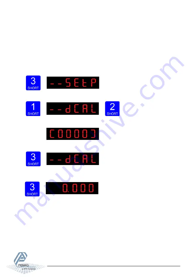
Press key 3 <2 sec. to go into the 

Main menu

Press key 1 <2sec. 2x to the 

dCAL 

menu and press key 2 <2sec. to enter. 


The following screen will show the actual CAL code. 


Press Key 3 <2 sec. to go back to the 

main menu


Press key 3 <2 sec. to go back to the 

main weigher display


Summary of Contents for SGM800

Page 1: ...PENKO Engineering B V Your Partner for Fully Engineered Factory Solutions Manual SGM800 Digitizer...

Page 2: ...instructions contact your Penko representative for clarification Pay careful attention to all warnings cautions and instructions marked on and supplied with the product Inform and educate your person...

Page 3: ...ed cable conduit entries must be securely sealed by non flammable blanking plates or blind grommets to ensure complete enclosure integrity in compliance with personal safety and environmental protecti...

Page 4: ...ANGE AND MULTI INTERVAL MODES 14 2 4 CONFIGURATION MENU STRUCTURE 16 2 5 DISPLAY INDICATION AT STARTUP 17 2 6 WEIGHER SETTINGS 18 2 7 CALIBRATION 21 2 8 PI MACH II SOFTWARE 24 3 MAIN MENU 32 3 1 CONFI...

Page 5: ...quate heat dissipation 30mm of space above and below the indicator are advised More space may be necessary for cables and connectors 101mm 120mm 6mm 30 50mm 30 50mm 1mm 200mm 10mm 22 5mm 30 50mm 101mm...

Page 6: ...by a Class 2 or Limited Power Source rate 18 32 Vdc 0 2A 24Vdc The shields of all connected interfaces must be earthed to a reference point e g the din rail Example Analogue output option Inputs Inpu...

Page 7: ...intended to be supplied by a Class 2 or Limited Power Source rate 18 32 Vdc 0 2A 24Vdc The shields of all connected interfaces must be earthed to a reference point e g the din rail Example Analogue ou...

Page 8: ...pplied by a Class 2 or Limited Power Source rate 18 32 Vdc 0 2A 24Vdc The shields of all connected interfaces must be earthed to a reference point e g the din rail Example Analogue output option Input...

Page 9: ...supplied by a Class 2 or Limited Power Source rate 18 32 Vdc 0 2A 24Vdc The shields of all connected interfaces must be earthed to a reference point e g the din rail Example Analogue output option In...

Page 10: ...lied by a Class 2 or Limited Power Source rate 18 32 Vdc 0 2A 24Vdc The shields of all connected interfaces must be earthed to a reference point e g the din rail Example Analogue output option Inputs...

Page 11: ...ded to be supplied by a Class 2 or Limited Power Source rate 18 32 Vdc 0 2A 24Vdc The shields of all connected interfaces must be earthed to a reference point e g the din rail Example Analogue output...

Page 12: ...re active 4 Output active 1 41 5 Weigher value 6 Profinet BUS state2 With cover opened 1 key 1 press 2sec 2 key 2 press 2sec key 1 press 2sec key 2 press 2sec 3 key 2 press 2sec key 2 press 2sec 1 Whe...

Page 13: ...value by 1 or move down inmenu Pressing key 2 short In Weighing mode set reset tare and reset preset tare In Menu mode go into sub menu or move cursor 1 position to the left Pressing key 2 long In Wei...

Page 14: ...three parameters are listed in the table below Parameter Value s Range Range size as integer Max step 1 2 5 10 20 50 100 200 500 Mode Multiple Range Multi Interval The output LED s are used to show th...

Page 15: ...cting an option in the dropdown menu The default value is 50 2 3 3 Multi Interval With these settings the weight indicator adjusts its display resolution up and down depending on the NET weight on the...

Page 16: ...ernet settings SGM820 only CAn Can bus port settings SGM830 only Pb Profibus settings SGM840 only 232 RS232 port settings SGM850 only 422 RS422 port settings SGM850 only Ind Indicator settings rng Mul...

Page 17: ...0 Ethernet Software version This is the software version installed in the device Software update counter The number of times that the software of the device is updated TAC code The Traceable Access Co...

Page 18: ...tor parameters pressing key 2 Use Ind 1 to set the maximum net weight value Set maximum load to prevent overload by the user The indicator will not show any weight above the filled in value Range 0 fu...

Page 19: ...ue The display value will be rounded off to the nearest value with a valid step size Use key 1 to select the correct step size Choose between 1 2 5 10 20 50 100 200 500 and confirm by pressing key 3 f...

Page 20: ...ine the point position and confirm by pressing key 3 for 2 sec Left Right Confirm Done successfully the following screen is visible Press key 3 2 sec to go back to Configuration Menu Press key 3 2 sec...

Page 21: ...and delete calibration points To enter the Calibration settings press key 2 2 sec The following screen is visible Press key 1 2 sec to go to CAL 3 and press key 2 2 sec Use CAL 3 to check and delete a...

Page 22: ...c to do so 3 sec When all calibration points are deleted the following screen is visible Entering new calibration points Use key 1 2 sec to go to CAL 1 and press key 2 2 sec After entering the followi...

Page 23: ...e value Key 1 is used for changing the number 1 9 key 2 is used for changing the position of the cursor Load the weigher with the reference value and press key 3 2 sec Up Down Left Right Confirm Done...

Page 24: ...nterface to configure all Penko devices Job Manager XE Version Control System for Pi Mach II projects Drivers USB drivers for latest series Penko devices Manuals Product manuals and protocol descripti...

Page 25: ...are disconnected from the PC In case of Windows 8 a USB driver manual is available in the Penko Suite In the communication setup it s also possible to connect the SGM820 through Ethernet Set the IP a...

Page 26: ...ings you can make are Unit set the weigher unit kg lbs T etc this will be shown in PI Decimal point Set the decimal point to show the correct weigher value Step Choose between 1 2 5 10 20 50 100 200 5...

Page 27: ...ttings to get a stable weigher signal The options are Unknown Standard indicator Fast indicator Silo Platform Belt slow Belt fast Filling slow Filling fast Checkweigher slow or Checkweigher fast Use s...

Page 28: ...rnet Here you can set Name here you can give the SGM820a name Example platform 1 Address set the IP address for the SGM820 Mask set the subnetmask for the SGM820 Gateway set the Gateway for the SGM820...

Page 29: ...MANUAL SGM800 29 SGM840 PROFIBUS Here you can set Address Set the Profibus address of the SGM840 Format Set the format of the values sent over Profibus Integer or Floating Point...

Page 30: ...SGM850 on the communication bus Stopbits set the stopbits of the SGM850 on the communication bus Paritiy set the parity of the SGM850 on the communication bus Options are None Odd Even Mark Space Bau...

Page 31: ...MANUAL SGM800 31 Use Done to finish the quick setup Click End Quick setup Click Enable Full setup to gain access to all settings optional The following tree is shown and gives access to all settings...

Page 32: ...ferent levels These levels have to be filled in at the setpoint menu Press key 3 2 sec to go into the Main menu Press key 2 2sec to the setpoint change menu Press key 1 2 sec to select a different set...

Page 33: ...indicator gets certified this number will be written on the device and is used by the controlling agency to see if the settings aren t changed after sealing To check out the TAC code Press key 3 2 sec...

Page 34: ...en on the device and is used by the controlling agency to see if the settings aren t changed after sealing To check out the CAL code Press key 3 2 sec to go into the Main menu Press key 1 2sec 2x to t...

Page 35: ...ate 3 1 Configuration Menu Press button 3 2 sec to enter the Configuration Menu In the Configuration Menu the following options are available Fun setpoint function settings not for SGM810 or controlle...

Page 36: ...m the selected output by pressing key 2 2 sec The following screen is visible Scroll thru the weigher function options pressing key 1 and select which weigher mode is needed by pressing key 3 2sec opt...

Page 37: ...e pressing key 1 2 sec Acn 1 output 1 Acn 2 output 2 Acn 3 output 3 and Acn 4 output 4 Confirm the selected out put by pressing key 2 2 sec The following screen is visible Fill in the hysteresis for t...

Page 38: ...MANUAL SGM800 38 Positive hysteresis Negative hysteresis...

Page 39: ...dAC 3 Set analog output to level in percetage dAC 4 Analog output weigher mode dAC 5 Zero value for minimum analog output dAC 6 End value for maximum analog output dAC 7 Analog output range Press key...

Page 40: ...0100 00 using key 1 and key 2 Key 1 is for changing the number 1 9 key 2 is for changing the position of the cursor Confirm by pressing key 3 2 sec Press key 3 2 sec to go back and reset the analog ou...

Page 41: ...19 Signal For further details on the weigher functions check appendix I The following screen will be visible In dAC 5 you set the weigher start value for the analog output At this value the analog out...

Page 42: ...Right Confirm The following screen will be visible In dAC 7 you set analog outputmode Press key 2 2sec to enter dAC 7 Scroll thru the weigher function options pressing key 1 and select which analog ou...

Page 43: ...set for communication with multiple devices Press key 2 2 sec to enter the settings The following screen will be visible In 485 1 you set the address of the SGM800 Press key 2 2sec to enter 485 1 Set...

Page 44: ...t address Sub 2 Second three numbers of the Subnet address Sub 3 Third three numbers of the Subnet address Sub 4 Fourth three numbers of the Subnet address gAt 1 First three numbers of the Gateway add...

Page 45: ...en will bevisible In Adr 3 you set the third three numbers of the IP address you want to give the SGM820 example 192 168 151 112 Use key 1 and key 2 to change the number Key 1 is for changing the numb...

Page 46: ...following screen will bevisible In Sub 2 you set the second threenumbers of theSubnet address you want to give the SGM820 example 255 255 255 000 Use key 1 and key 2 to change the number Key 1 is for...

Page 47: ...9 key 2 is for changing the position of the cursor Confirm by pressing key 3 2 sec Increase Decrease Left Right Confirm When confirmed the following screen will bevisible In gAt 1 you set the firstnum...

Page 48: ...ateway address you want to give the SGM820 example 192 168 001 001 Use key 1 and key 2 to change the number Key 1 is for changing the number 1 9 key 2 is for changing the position of the cursor Confir...

Page 49: ...MANUAL SGM800 49 When confirmed the following screen will bevisible Starting at firmware version 1 5 0 9 0 1 the PENKO ASCII protocol is available over TCP at port 23...

Page 50: ...profibus Options are Pb 1 Profibus address Pb 2 Value mode Press key 2 2 sec to enter the profibus settings The following screen will be visible In Pb 1 you set the profibusaddress of the SGM840 Pres...

Page 51: ...point Press key 2 2 sec to change the mode The options are Pb2 FL Floating point Pb2 In Integer Select the option you want to use by pressing key 1 and confirm by pressing key 3 2 sec Increase Decreas...

Page 52: ...2 sec to enter the RS232 port settings The following screen will be visible In 232 1 you set the RS232 Protocol of the SGM850 Press key 2 2 sec to en ter 232 1 Set the Prot using key 1 and key 2 confi...

Page 53: ...are 0 255 Increase Decrease Left Right Confirm When confirmed the following screen will bevisible In 232 3 you set the RS232 stopbitsof the SGM850 Press key 2 2 sec to enter 232 3 Set the number of st...

Page 54: ...ace Increase Decrease Confirm When confirmed the following screen will be visible In 232 5 you set the RS232 Baudrate of the SGM850 Press key 2 2 sec to en ter 232 5 Set the speed of the protocol by u...

Page 55: ...s effect when using the ASCII protocol Press key 2 2 sec to enter 232 6 Set the Indicator number that you want to send out over the RS232 port by using key 1 and key 2 confirm by pressing key 3 2 sec...

Page 56: ...2 sec to enter the RS422 port settings The following screen will be visible In 422 1 you set the RS422 Protocol of the SGM850 Press key 2 2 sec to enter 422 1 Set the Prot using key 1 and key 2 confi...

Page 57: ...set the RS422 stopbitsof the SGM850 Press key 2 2 sec to enter 422 3 Set the number of stopbits the protocol needs by using key 1 and key 2 confirm by pressing key 3 2 sec options are 1 2 Increase Dec...

Page 58: ...00 6 38400 7 57600 8 115200 kbps Increase Decrease Confirm When confirmed the following screen will be visible In 422 6 you set the RS422 ASCII Indicator of the SGM850 This setting only ta kes effect...

Page 59: ...5 Display step size Ind 6 Decimal point position Ind 7 Display refreshment speed Ind 8 Operation mode Ind 9 Sample time Press key 2 2 sec to enter the indicator settings The following screen is visib...

Page 60: ...ge and time set with Ind 3 Choose a value between 0 999999 To change the value press key 2 2sec The following screen is visible Use key 1 and 2 to change the value Key 1 is for changing the number 1 9...

Page 61: ...he overall filter to effect all indicator signals used in the device 0dB means no effect and 50dB is the strongest damping Choose between 0dB 1 6dB 2 12dB 3 24dB 4 30dB 5 36dB 6 42dB and 7 50dB To pre...

Page 62: ...off to the nearest value with a valid step size To change the display step size press key 2 2 sec The following screen is visible Use key 1 to select the correct step size Choose between 1 2 5 10 20 5...

Page 63: ...ble Press key 1 to define the point position and confirm by pressing key 3 for 2 sec Left Right Confirm The following screen is visible In Ind 7 you set the Display refreshment speed The Display refre...

Page 64: ...In certified mode the unit will be sealed by marks and also the weighing parameters will be blocked to satisfy to the cali bration laws A weighing unit must be certified when it s used for measuring...

Page 65: ...esh ment speed of the weigher signal Options are 10 20 25 50 100 200 400 800 1600 samples sec To change the sample rate press key 2 2 sec The following screen is visible Press key 1 to choose the samp...

Page 66: ...Press key 2 2 sec to enter the multi range interval settings The following screen is visible In rng 1 you set the number of displaydivisions Set the number of divisions when the indicator has to displ...

Page 67: ...own Left Right Confirm The following screen is visible In rng 2 you set the maximumauto range step size Set the biggest step size al lowed Choose between 1 2 5 10 20 50 100 200 and 500 To change the m...

Page 68: ...The following screen is visible In rng 3 you set the auto range reset option Choose between of Multi Range the highest shown step size will be reset after the signal has been lower or equal to zero on...

Page 69: ...ess key 2 2 sec to enter the filter settings In FIL 1 you can set the display filter band Set the band where the filter is active This parameter works together with FIL 2 Choose a value between 99999...

Page 70: ...the filter Confirm by pressing key 3 for 2 sec Up Down Confirm The following screen is visible In FIL 3 you set the band within the indicator will show 0 When the indicator is certified this parameter...

Page 71: ...10 3 Fast net 12 Fast Net x 10 4 Display Gross 13 Display Gross x 10 5 Display Net 14 Display Net x 10 6 Tare 15 Tare x 10 7 Peak 16 Peak x 10 8 Valley 17 Valley x 10 9 Hold 18 Hold x 10 19 Signal For...

Page 72: ...average cutoff frequency Press key 2 2 sec to enter the digital filter settings The following screen is visible In dSF 1 you can set the filter type Choose between None Dynamic and Static Dynamic app...

Page 73: ...Hz and 40Hz Press key 2 2 sec to change the cutoff frequency range The following screen is visible Use key 1 change the cutoff frequency Confirm by pressing key 3 for 2 sec Up Down Confirm The followi...

Page 74: ...ssing key 3 for 2 sec Up Down Left Right Confirm The following screen is visible PCL Pre calibration settings In this menu the Pre calibration settings can be set Options are Pcl 1 Polarity of input r...

Page 75: ...itity og the input range The following screen is visible Use key 1 change the polarity Confirm by pressing key 3 for 2 sec Up Down Confirm The following screen is visible In PcL 2 you can set the Ampl...

Page 76: ...is for changing the position of the cursor Confirm by pressing key 3 for 2 sec Up Down Left Right Confirm The following screen is visible In PcL you can Recall the Pcl parameters The PcL parameters w...

Page 77: ...how remove calibration points CAL 4 Deadload compensation CAL 5 Show CAL code Press key 2 2 sec to enter the calibration settings The following screen is visible In CAL 1 you can set the calibrationpo...

Page 78: ...used for changing the number 1 9 key 2 is used for changing the position of the cursor Load the weigher with the reference value and press key 3 2 sec Up Down Left Right Confirm Done successfully the...

Page 79: ...value When finished press key 3 2 sec The following screen is visible Use CAL 3 to check and delete all existingcalibrationpoints Press key 2 2 sec to enter CAL 3 The following screen is visible Step...

Page 80: ...is menu the deadload can be set to pull the whole weighing line back to zero The zero point could be differ and because of some modification on the scale or dirt Press key 2 2 sec to set a new deadloa...

Page 81: ...y the deadload is zero but it is possible to change the line position if there is weight on the scale To do so edit the actual weigh value to the new known value When the new dead load is set the foll...

Page 82: ...ptions are tCL 1 Maximum load loadcells tCL 2 Sensitivity loadcell 1 tCL 3 Sensitivity loadcell 2 tCL 4 Sensitivity loadcell 3 tCL 5 Sensitivity loadcell 4 Press key 2 2 sec to enter the theoretic cal...

Page 83: ...u can set the loadcell sensitivityfor loadcell 1 This information can be found on the datasheet delivered with the loadcell Press key 2 2 sec to set the loadcell sensitivity The following screen is vi...

Page 84: ...nsitivity of loadcell 2 Key 1 is used for changing the number 1 9 key 2 is used for changing the position of the cursor Sensitivity has to be filled in as 0 00000 mV V Press key 3 2 sec to set the sen...

Page 85: ...loadcell 4 This information can be found on the datasheet delivered with the loadcell Press key 2 2 sec to set the loadcell sensitivity The following screen is visible Use key 1 and key 2 to enter th...

Page 86: ...ter the Geographic calibration settings The following screen is visible In gcL 1 you can set the originlatitudeof the loadcell This is the geographic latitude of where the loadcell is manufactured Pre...

Page 87: ...1 and key 2 to enter the origin elevation of the loadcell s Key 1 is used for changing the number 1 9 key 2 is used for changing the position of the cursor And press key 3 2 sec to set the origin ele...

Page 88: ...en is visible In gcL 4 you can set the location elevation of the loadcell This is the geographic elevation of where the loadcell is going to be used Press key 2 2 sec to set the location elevation The...

Page 89: ...ey 2 to change the number Key 1 is for changing the number 1 9 key 2 is for changing the position of the cursor Confirm by pressing key 3 2 sec Format DD MM YY The following screen is visible Set the...

Page 90: ...g screen is visible There are two recalls available Parameters back to factory or an erase of the file system Use the erase function only when a normal recall does not solve the problem To set all par...

Page 91: ...y be made using Pi Mach II manage Enter the password in the service code field The backup can be made in the Factory Recall menu Restore Parameters only restores the non certified parameters This opti...

Page 92: ...3 1 19 Menu SoF SoF Firmware update In SoF you can set the SGM800 in boot mode for software update Press key 2 2 sec to enter Boot mode The following screen is visible Press key 3 2 sec to set the SGM...

Page 93: ...gh USB Start PI Mach II Set communi cation to USB Start the Firmware Update Manager Click Open and select the PIP file Click Search For Devices and select the device with source 0 Use double click or...

Page 94: ...ar Go to SoF by pressing key 1 2 sec until you see SoF Press key 2 2 sec to enter Boot mode The following screen is visible Press key 3 2 sec to set the SGM800 in Boot mode Now click Firmware Update t...

Page 95: ...PI Mach II Manage is explained in chapter 3 of this manual Enter the Event number at Entry Number and confirm with Enter or the Apply button The event is shown In this example you can see that Entry...

Page 96: ...MANUAL SGM800 96 complete Event log memory...

Page 97: ...In the SGM800 Belt the Alibi Memory has no function The Alibi memory can be viewed via Pi Mach II Manage How you can connect your SGM800 to PI Mach II Manage is explained in chapter 3 of this manual E...

Page 98: ...and confirm with Enter or the Apply but ton The Alibi data is shown It shows the weigher value that is saved with the time and date it is saved on Events can only be printed with the SGM850 Serial Pr...

Page 99: ...ase check the SGM800 Check weigher manual supplement To get the Alibi information enter the Alibi number at Entry Number and confirm with Enter or the Apply button The Alibi data is shown It shows the...

Page 100: ...please check the SGM800 Mono Filler manual supplement To get the Alibi information enter the Alibi number at Entry Number and confirm with Enter or the Apply button The Alibi data is shown It shows th...

Page 101: ...rithmetic overflow occurred Change calibration levels 2106 A D reads all 1 s Check load cell connection 2107 A D reads all 0 s Check load cell connection 2108 Gain ref zero ref Change calibration leve...

Page 102: ...or Code Description Solution CCCCCC No proper calibration available Check calibration setting UUUUUU Underflow Check loadcell Check platform construction OOOOOO Overflow Check loadcell Check platform...

Page 103: ...Status byte 8 bit Reserved byte 8 bit Weight selected register Outputs from PLC word 16 inputs Input 1 16 byte 8 bit Command word 16 outputs Output 201 216 byte 8 bit Weight selector register D word 3...

Page 104: ...Fun 1 1 Fun 2 1 Fun 3 1 Fun 4 1 Setpoint action Acn 1 000 010 Acn 2 000 010 Acn 3 000 010 Acn 4 000 010 Analog output dAC 4 2 dAC 5 000 000 dAC 6 010 000 dAC 7 4 Local bus communication 485 1 1 Profib...

Page 105: ...2 0 gAT 3 0 gAT 4 0 Indicator Ind 1 10 009 Ind 2 2 Ind 3 1 000 Ind 4 Ind 5 1 Ind 6 Ind 7 25 Ind 8 In Ind 9 1 60 Multi range interval Rng 1 0 Rng 2 1 Rng 3 oF Filter FIL 1 0 FIL 2 FIL 3 0 Digital filt...

Page 106: ...UAL SGM800 106 Pre calibration Pcl 1 un Pcl 2 2 0 Pcl 3 0 Theoretic calibration tCL 1 10 000 tCL 2 0 000 tCL 3 0 000 tCL 4 0 000 tCL 5 0 000 Geographic calibration gCL 1 52 00 gCL 2 0 gCL 3 52 00 gCL...

Page 107: ...er value shown with extra decimal that can react on multi range multi interval Fast Gross x 10 unfiltered gross weigher value shown with extra decimal Fast Net x 10 unfiltered bet weigher value shown...

Page 108: ...every project managing supporting and or implementing your system every step of the way Curious to know how we do it www penko com Certifications PENKO sets high standards for its products and produc...

Reviews: