


Trigger Hold-Off
In this menu you can set the delay during which the stop trigger
conditions are ignored after the measurement start. A typical use
is to clean up signals generated by bouncing relay contacts.
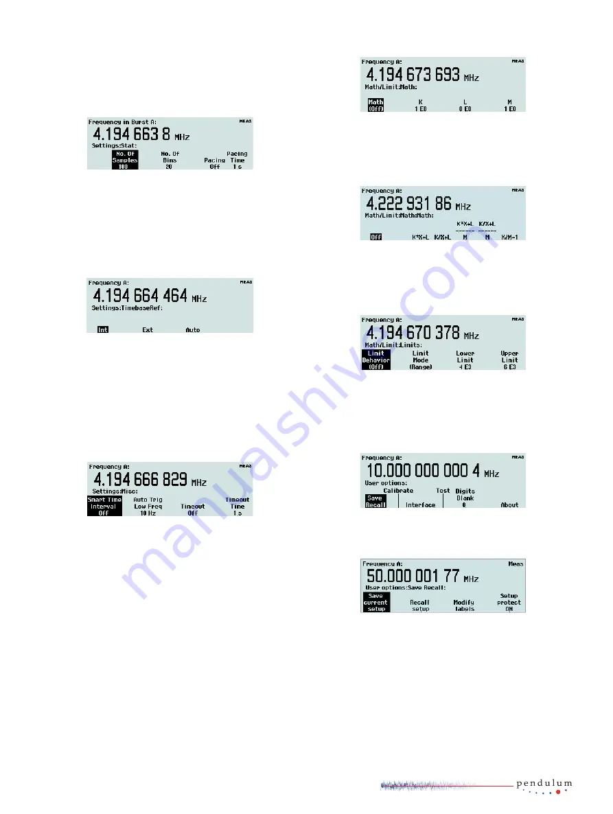
Statistics
In this menu you can find the following submenus:
•
No. of Samples: Set the number of samples used for calculation of
various statistical measures.
•
No. of Bins: Set the number of bins used in the histogram mode.
•
Pacing: Set the delay between successive measurements, called
Pacing Time, to ON or OFF.
•
Pacing Time: Set the pacing time to a value between 2 µs – 1000 s.
Timebase Reference
Here you can select if the counter is to use the internal or an
external timebase reference. If Auto is selected, an external
timebase will be used only if it is interpreted as a valid signal,
i.e. both amplitude and frequency must be within specified
limits. This does not imply, however, that an external reference
source has to be better in any sense than the internal timebase
oscillator. The EXT REF indicator at the upper right corner of the
display shows that the instrument is using an external timebase
reference.
Miscellaneous
The options in this menu are:
•
Smart Time Interval: When selected, the counter decides by means of
timestamping which measurement channel is leading.
•
Auto Trig LF: In a value input menu you can set the lower frequency
limit for automatic triggering and voltage measurements in the
range 1 Hz – 100 kHz. A higher limit means faster settling time and
consequently faster measurements.
•
Timeout
Switch the Timeout function ON or OFF. In case the input signal
gets interrupted, the timeout system (if enabled) will hold the last
measurement result on screen only during the selected period of time
(see next paragraph). Then the screen will be blanked, and a pending
bus query will read a zero result. In case timeout is switched off when
the signal gets interrupted, the display will freeze, i.e. the result of
the last complete measurement will stay on screen indefinitely. A
pending bus query will also wait indefinitely for a response, unless
the test system controller has enabled its own timeout.
•
Timeout Time
Set the maximum time the instrument will wait for a pending
measurement to finish before outputting a zero result. The range is
10 ms to 1000 s.
•
Math/Limit
Here you will find the menus for mathematical postprocessing of the
measurement result and for setting up the limit testing function.
Math
You can modify the measurement result mathematically by
scaling or offsetting before presentation on the display. This
feature can be used for getting revolutions/min instead of
Hz or for recalculating the frequency in case a device causing
frequency conversion (e.g. a multiplier or a mixer) is part of the
system under test.
Select one of four formulas and enter the constants K, L and M to
make the counter show directly what you want, without tedious
recalculations. X stands for the current unmodified measurement
result. See the User’s Manual for a closer description.
Limits
This menu is used for setting numerical limits and selecting
the way the instrument will report the measurement results in
relation to them. See the section Presentation Modes on page
3-4 for a short description or the User’s Manual for a more
detailed description.
User Options
From this menu you can reach a number of functions that are not
directly involved in the measurement process.
Save/Recall Menu
Twenty complete front panel setups can be stored in nonvolatile
memory; the first ten of them can be user-protected. The
different setups can be individually labeled to make it easier for
the operator to remember the application.
The following can be done:
•
Save Current Setup: Select one of twenty positions.
•
Recall Setup: Here you will find a factory-programmed default setup
as well as any setups you may have stored before.
•
Modify Labels: The seven soft keys right below the display plus the
numeric input keys 6, 7, 8, 9, 0 are used for entering lower-case
letters and digits much in the same way as you write SMS messages
on a cell phone. Each label can hold seven characters.
9


