6
11
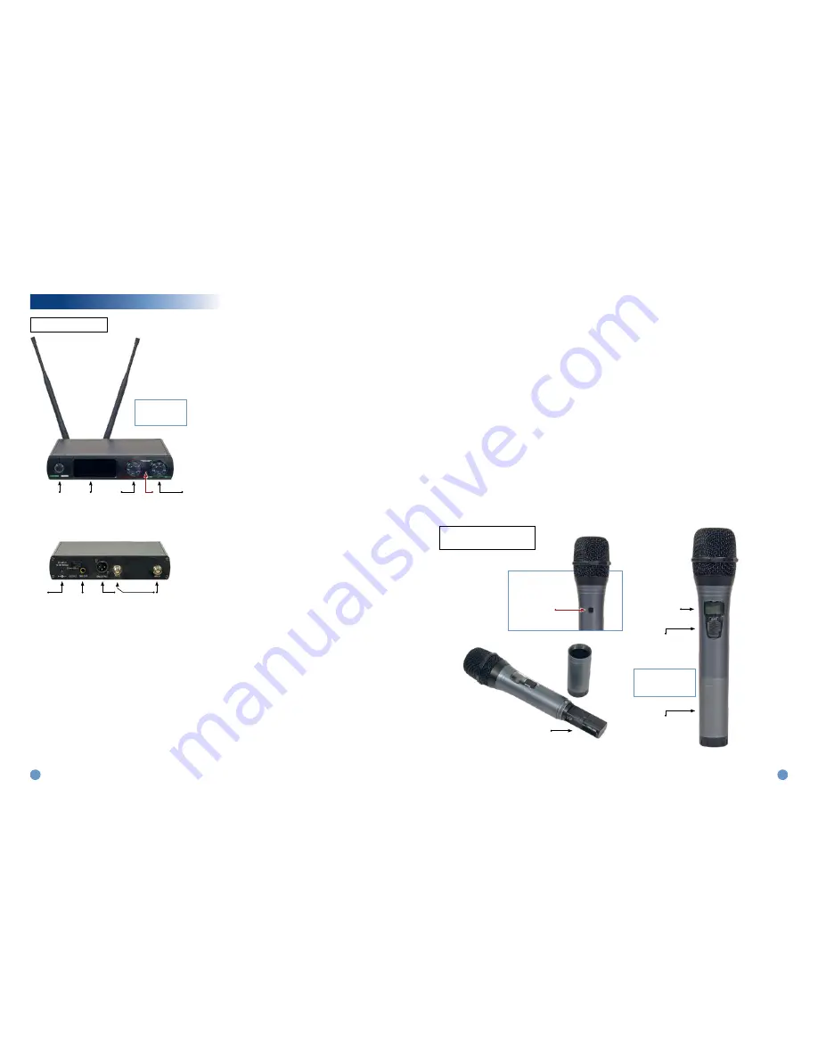
Helpful Diagrams
Power
Switch*
Botón de
Encendido
LCD Display
(Frequency
displayed here)
Receiver
Controller
Controlador
Recibidor
IR Sync
Window
Volume
Control
Control de
Volumén
FRONT
Antennae
Locations
¼" TRS
Output
Mezcla de
Salida Cable
Power Cord
Input
Entrada de Cable
de Energía
BACK
XLR Output
How to access Ir Sync Mode
Step 1. Make sure all other microphone receivers and
transmitters in the room are turned off except for
the receiver and transmitter you are trying to sync.
Step 2. Turn the “Receiver Controller” knob/button in blue
letters in diagram to the right until the LCD display
shows “IR Y/N”
Step 3. When the LCD display shows “IR Y/N” press the
knob/button into the unit.
Step 4. After pressing the knob into the unit it will show
IR- - - -. The - - - - lines will be moving. The
Receiver is now in IR Sync Mode.
Step 5. Now hold the powered on transmitter up to the
receiver with IR window facing toward the “IR”
location on receiver. See page 13 for an example.
Step 6. When the receiver and transmitter connect prop-
erly the LCD display on the receiver will read “IR
OK”. The frequency displayed on your transmitter
and receiver should match.
Step 7. The receiver and transmitter are now in sync and
the system is ready for use.
Other Functions:
the receiver controller will access the following
modes:
To select mode turn the receiver knob until you see the
desired mode. When you see the desired mode press but-
ton once. After selecting mode you can use the knob turn-
ing it right or left to change mode. Press button again once
desired setting is displayed on the LCD Display on the
receiver.
Mode options:
(A) Fre – Frequency Selection Mode
(B) CH – Channel Selection Mode
(C) IR – IR Y/N
(D) Scan – Scan Mode
(E) POW – HIGH or LOW
(F) LOCK – LOCOFF or LOCON
A. Fre (Frequency Selection Mode) – Press button once
and the frequency will begin to blink. Now you can
rotate the receiver knob to scroll through the frequency
options. When you find your desired frequency option
press the button once to select that frequency.
B. CH (Channel Selection Mode ) – 10 channel frequency
options. Press button once and the channel will begin
to blink. Now you can rotate the receiver knob to scroll
through the channel options of 1 through 10. When you
find your desired channel then press the button once to
select that channel. Note: The channel is a frequency.
C. IR (IR Y/N) – Press button once and you should enter
IR sync mode. This mode allows you to sync your
transmitter and receiver to the same frequency (or
channel).
D. Scan – Press button once to select scan mode. This
mode allows a scan for an available channel.
E. High or Low – Press button once on “High” or “Low”
to select. Rotate knob to set what strength setting you
desire. “High” should be used if the speaker may be
at a distance from the receiver. “Low” can be used if
the speaker will be close to the receiver. Batteries may
possibly drain more slowly at the “Low” setting. Press
button again once your desired setting is displayed on
receiver in LCD Display.
F. “LOCOFF” or “LOCON” – Press button once on
“LOCOFF” or “LOCON” to select mode. Rotate knob to
select. When in LOCON position receiver is locked in
all settings. Must turn to LOCOFF to readjust settings
on your receiver. Press button again once your desired
setting is displayed on receiver in LCD Display.
* Hold power button
for 3 seconds to
power on.
On/Off
Switch
Botón de
Encendido
Battery
Compartment
LCD
Display
(Frequency
displayed
here)
FRONT
BACK
IR Window
Location
Battery Compartment
Unscrew bottom of handle
to insert 2 AA batteries.
Three position switch.
Half-way between on/off
position is mute.
C. IR Sync
D. Back
Step 3. Using the top two buttons which operate move-
ment up and down scroll down to IR Sync. Once
you get to IR Sync press the Enter/Set button
which is the thrid button down from the top.
Step 4. After completing the step above you should have
the following four options for each of your receiver
channels and transmitters (A, B, C, and D):
IR SYNC A
IR SYNC B
IR SYNC C
IR SYNC D
Use the top two buttons to pick which transmitter
and channel you would like to sync. You can use
one channel per transmitter. One transmitter can
sync to A, the second can sync to B, the third to
C, and the fourth transmitter can sync to D. When
you toggle to the chosen channel hit the Enter/
Set button which is the third down from the top to
select your desired channel.
Step 5. After completing the previous step the receiver
should now be ready to sync for the channel you
have chosen. Now hold the powered on trans-
mitter up to the receiver with IR window facing
toward “IR” location on receiver. See diagram on
preceding page to find location on your receiver.
Step 6. After successfully completing the IR Sync pro-
cedure repeat the same procedure for all for 4
transmitters choosing a different channel (A, B,
C or D) for each transmitter. Each transmitter
must be on a different frequency. If you have two
receiver channels on the same frequency then
use the “Fre Select” function to change the fre-
quency or "channel" for that transmitter.
Note: Using Group select will pick four different preset fre-
quencies for each of your transmitters. You will still
need to use IR Sync to sync each transmitter with
the receiver.
PM-WP1 Series
PM-hhP1 handheld
transmitter


