Visit the Peerless Web Site at www.peerlessmounts.com
ISSUED: 03-23-09 SHEET #:055-9260-5 09-26-12
3 of 9
PSTA-028
PSTA-028-W PSTK-028
PSTK-028-W
Description
Qty. Part #
Part #
Part #
Part #
A
wall arm
1
055-1909
055-2909
055-1909
055-2909
B
carriage 1
055-1915
055-2915
055-1915
055-2915
C
4 mm allen wrench
1
560-9646
560-9646
560-9646
560-9646
D
M5 x 10 mm serrated socket pin screw
4
520-1063
520-2063
520-1063
520-2063
E
#14- x 2.5 phillips head wood screw
4
5S1-015-C03 5S1-015-C04 5S1-015-C03 5S1-015-C04
F
tube cap
1
590-1274
590-1274
590-1274
590-1274
G
concrete anchor
4
590-0320
590-0320
590-0320
590-0320
H
1/4"-20 phillips screw
2
520-1054
520-2069
520-1054
520-2069
I
1/4"-20 flat washer
2
540-1078
540-2078
540-1078
540-2078
J
PRG-UNV
1
PRG-UNV PRG-UNV-W PRG-UNV PRG-UNV-W
K
wall plate
1
—
—
055-1923
055-2923
L
5/16 -18 x 1/2 carriage bolt
4
—
—
520-9207
520-2047
M
5/16 - 18 serrated flanged lock nut
4
—
—
530-1016
530-2016
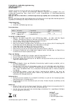
Parts List
A
B
Before you start check the parts list to insure all of the parts shown are included.
IMPORTANT:
Read instruction sheet before you start installation and assembly.
NOTE:
Some parts may appear slightly different than illustrated.
E
F
D
G
C
H
J
I
K
L
M