background image

© COPYRIGHT 2010 PECO, INC.  ALL RIGHTS RESERVED.   


P/N 70476 3220-2265 REV 00 

5

sYstem test Fan: oPtIonal

If continuing from the previous section on this page, skip to Step 2 below. The following 

instructions assume that the user enters the Service Menus from the home screen display; 

it does not assume that the user has followed in sequence from the previous section. 

1.  On the thermostat, press the lower left and lower right keys simultaneously for about 

fi ve seconds. 

Next

,


Go Back

, and 

Done

 appear (see Fig. 12).

2.  Press 

Next

 until Service Menu 620 appears in the display. 

( The default value for Service Menu appears below Service Menu.) 

3.  In Service Menu 620, press ▲/ ▼to select option “01” to enable fan output 

(see Fig. 13).

note:

 If 1 is selected, the thermostat will activate the associated output for 10 minutes. 

The user should observe that the fan output will turn on. 

4.  Press 

Done

 to complete the system test. After verifying the system test, the outputs 

are disabled. 

optional: the user may also perform system test main output (cool):see table 2, 

service menu 600. 

User oPeratIon

For detailed instructions on user operation of the T4000 Series, including how to operate 

all key functions, please refer to the Performance PRO T4000 Series Operating Manual, 

the companion to this installation guide. 

Part X: set PIn access For servIce menUs (oPtIonal)

Creating a PIN access code allows the installer to restrict access to Service Menus. First,  

PIN access must be enabled in Service Menu 341; second, a three-digit code must be 

created in Service Menu 342. After these two Service Menus are properly confi gured, the 

thermostat requires the user to enter a PIN access code to enter the Service Menus.  

1.  On the thermostat, press the lower left and lower right keys simultaneously for about 

fi ve seconds. 

Next

,


Go Back

, and 

Done

 appear (see Fig. 14).

2.  Press 

Next 

until Service Menu 341 (Enable/Disable PIN Access) appears in the 

display. (Default value “00” appears below Service Menu.) 

3.  In Service Menu 341, press ▲/ ▼to change digit (fl ashing) value to “01” (see Fig. 14). 

note: selecting 01 enables PIn access for the thermostat service menus, and 

selecting it is necessary to show service menu 342.


4.  Press 

Next

5.  In Service Menu 342, press ▲/ ▼adjust values and create a three-digit PIN access 

code. The fl ashing three-digit code appears in the clock area (see Fig. 15). 

note: write down the PIn access code, and keep it in a safe place. 


6.  Press 

Done

 when fi nished.

verIFY PIn access coDe 

Enter the PIN access code upon entering the Service Menus. Note: Flashing digit is active; 

it is changed using the ▲/ ▼keys. The active (editable) digit moves 

from right to left.


1.  On the thermostat, press the lower left and lower right keys simultaneously for about 

fi ve seconds. 

note 

Flashing three-digit code, 

Next

, and 

Done

 appear (see Fig. 16).

2.  Press ▲/ ▼to change value of digit furthest to the right, then press 

Next

3.  Press ▲/ ▼to change value of digit in middle, then press 

Next

4.  Press ▲/ ▼to change value of digit furthest to left, then press 

Done

note

: After step 4 is complete, user is allowed access to Service Menus. 

Next

,


Go Back

Done,

 and Service Menu 100 appear.
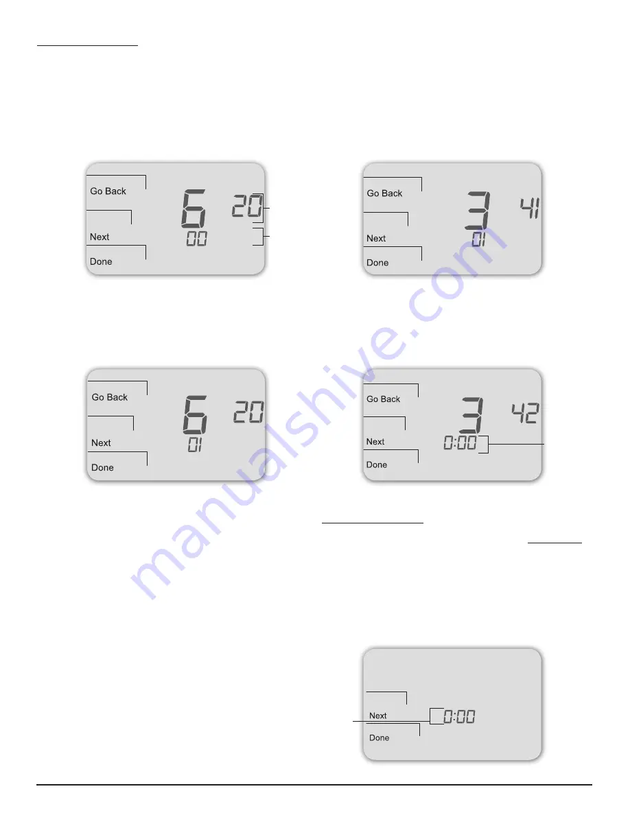
Figure 13. 

Press Done 

to complete 

testing and 

exit Service 

Menus, 

or Next to 

continue tests. 

Figure 14. 

Service Menu 

341 allows 

user to restrict 

access to 

Service 

Menus.

Figure 12.  

Service Menu 

620 allows 

the user to 

perform a 

System Test 

Fan.

Service Menu

Default value 

(appears 

automatically)

Figure 15. 

Service Menu 

342 allows 

user to create 

a PIN access     

code.

Flashing 

three-digit 

code

Figure 16. 

PIN access 

code fl ashes 

when user 

enters Service 

Menus (after 

enabling PIN 

access). 

Flashing 

three-digit 

code

Summary of Contents for Perfomance PRO T4500

Page 1: ...nd heat pump applications System mode selections Off Heat Cool Auto Stages 1 Heat 1 Cool 2 Heat 1 Cool 1 Heat 2 Cool 2 Heat 2 Cool 3 Heat 2 Cool Fan control Cycling Auto or Continuous On 1 Speed Permanent memory All device settings are stored in permanent memory Connections for Remote Sensors indoor and occupancy caUtIon 24 vac low voltage thermostat Do not install on voltages higher than 30 vac U...

Page 2: ... side 24 VAC sc Sensor Common sc Sensor Common s1 Indoor Remote Sensor s1 Indoor Remote Sensor System Type 1 1H 1C Conventional System Type 2 1H 1C Heat Pump TERM Function TERM Function C Common C Common W1 Heat B O Reversing Valve W2 AUX G Fan G Fan A A E E Y1 Cool Y1 Compressor Y2 Y2 RH Power for Heating RH Power for Heating RC Power for Cooling RC Power for Cooling System Type 3 Heat only witho...

Page 3: ...allplate Assure that the metal jumper connects RC and RH Connect power side to the RC RH and assure that the jumper remains in place two transformer system The T4000 T4500 is shipped with a jumper connecting terminals RH and RC If the heating and cooling equipment do not use separate transformers leave this jumper in place If separate transformers are required remove this jumper With the jumper re...

Page 4: ...wIth sYstem tests System test verification is highly recommended to verify thermostat operation Follow at least one procedure in the system tests below Refer to the Service Menus see Table 2 for more tests For all tests press next to continue to the following system test which is the next available Service Menu Press Done only if finished performing all system tests Pressing Done exits the Service...

Page 5: ...ostat press the lower left and lower right keys simultaneously for about five seconds Next Go Back and Done appear see Fig 14 2 Press Next until Service Menu 341 Enable Disable PIN Access appears in the display Default value 00 appears below Service Menu 3 In Service Menu 341 press to change digit flashing value to 01 see Fig 14 note selecting 01 enables PIn access for the thermostat service menus...

Page 6: ...ntrols heating fan 130 Changeover valve B O terminal 0 1 0 0 B O terminal controls valve in cooling 1 B O terminal controls valve in heating 140 Auxiliary Heat 0 1 0 0 Electric backup heat 1 Fossil fuel backup heat 150 Backlight 0 1 0 0 Backlight temporarily on 1 Backlight always on low intensity 24V only 170 Remote Sensor 0 1 0 Select sensor if used connected to the S1 Terminal Contact PECO for m...

Page 7: ...eduled event 1 1 Hour 2 2 Hours 3 3 Hours 4 4 Hours 400 Cycles Per Hour CPH Cooling Stage 1 0 6 CPH 3 CPH Defines the number of cycles per hour for cooling Stage 1 Select 0 to enable ON OFF control for Stage 1 cooling 410 Cycles Per Hour CPH Cooling Stage 2 0 6 CPH 3 CPH Defines the number of cycles per hour for cooling Stage 2 Select 0 to enable ON OFF control for Stage 2 cooling 420 Cycles Per H...

Page 8: ...Disable 1 Enable Note Press Done key to complete process 600 System Test Main Output Cool 0 2 0 Select an option to activate the fan output for 10 minutes select 0 Done or a different Service Menu to disable 0 Disable Default 1 Cool Stage 1 2 Cool Stage 2 610 System Test Main Output Heat 0 3 0 Select an option to activate the fan output for 10 minutes select 0 Done or a different Service Menu to d...

Page 9: ...resent check wire connection between the heating equipment and the thermostat If Demand Indicator light is red Heating is occurring No action is required If Demand Indicator light is green Cooling is occurring No action is required If Demand Indicator light is flashing An error has occurred Remote sensor may be malfunctioning Check remote sensor wiring Verify that the sensor s are PECO supported p...

Page 10: ...Unt Peco InDoor remote zone sensor sP155 017 warnInG READ THESE INSTRUCTIONS CAREFULLY BEFORE ATTEMPTING TO INSTALL OPERATE OR SERVICE THIS SENSOR Failure to observe safety information and comply with instructions could result in PERSONAL INJURY DEATH AND OR PROPERTY DAMAGE To avoid electrical shock or damage to equipment disconnect power before installing and use only wiring with insulation rated...

Page 11: ...sor maXImUm lenGth anD wIre sIze Distance from Unit to control recommended wire size 000 150 feet 22 gauge 151 240 feet 20 gauge 241 385 feet 18 gauge 386 610 feet 16 gauge 611 970 feet 14 gauge wIrInG 1 run wires Run wires between the thermostat wallplate and the Zone Sensor subbase 2 connect wires Connect the wiring to the terminals S1 and SC at the thermostat wallplate see Fig 22 note See TABLE...

Page 12: ...or message If the Indoor Remote Zone Sensor is not connected properly check the following Make sure sensor is wired properly and connected to terminals S1 and SC on the thermostat wallplate see Table 1 Terminal Designations and System Types If using multiple sensors make sure wiring follows diagrams in Sensor Wiring for Temperature Averaging Make sure to select 01 in Service Menu 170 Figure 25 The...

Reviews: