9
S t a t i o n F o u r - W O p e r a t i o n
▲
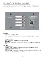
LED color indicates status of each of the four Zone presets.
▲
Green indicates the zone is available and not in use by another station.
▲
Red indicates the zone is in use.
▲
When the microphone ÒTalkÓ button is pressed, the selected zone preset LED turns orange to
confirm that it is active. Other stations connected to the system will indicate RED to confirm
that this particular zone is in use.
▲
Press any Zone Preset button to select. The LED will blink confirming the selection.
▲
At power-up, the unit defaults to zone one and after one minute of inactivity reverts back to
zone one.
▲
Hand-held 5-pin mic input is activated by pressing the ÒtalkÓ button.
▲
Zone presets can be labeled in the appropriate white boxes.
▲
If all LEDs flash red at power up, this indicates the station has not been programmed.
▲
If all LEDs flash green at power up, this indicates the station has been
programmed.
A b o u t Z o n e P r e s e t s
MediaMatrix defines the zones which can represent single outputs or groups of outputs. PageMatrix
software is used to program the button assignments on the paging stations which enables them to
access one or more zones per button. We refer to the button assignments as zone presets, since
these settings are set initially. They are then downloaded to the PageMatrix controller where they
become active.
A b o u t P r i o r i t y
With PageMatrix, there are no inherent priority settings. Any microphone may be used at any time
and the ÒbusyÓ LED indication identifies when a zone preset is in use by another station. However,
extensive priority levels can be configured and designed within MediaMatrix.
Summary of Contents for PageMatrix
Page 1: ...ARCHITECTURAL ACOUSTICS O W N E R S M A N U A L PAG E MAT R I X Controller...
Page 25: ...5 4 5 Pin Wiring Diagram 25 Mic Switch GND Audio Audio...
Page 48: ...5 4 5 P i n M i c W i r i n g D i a g r a m Mic Switch GND Audio Audio 48...
Page 72: ...Mic Switch GND Audio Audio 5 4 5 Pin Wiring Diagram 72...
Page 96: ...Mic Switch GND Audio Audio 5 4 5 Pin Wiring Diagram 96...
Page 100: ...100 NOTES...
Page 101: ...101 NOTES...


