background image


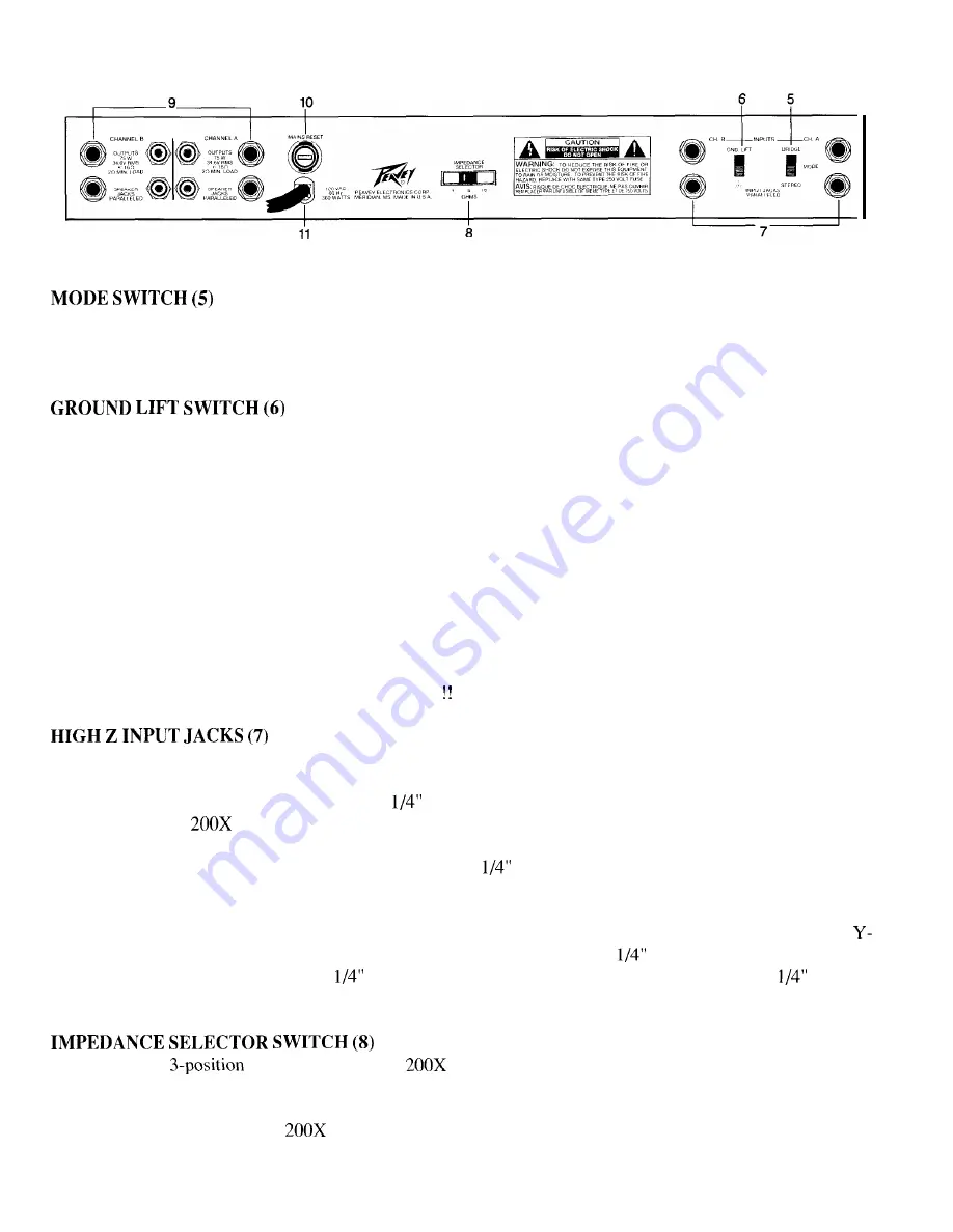
This switch is used to select either STEREO or BRIDGE mode of operation. Care should be exercised whenever
the BRIDGE mode is selected. Accidental selection of this mode could damage loudspeakers, particularly in
BIAMPED systems. (The BRIDGE mode will be covered in greater detail later in this manual.)


This switch is used to disconnect the unit’s signal ground (both input and output) from the “chassis ground.”
Chassis ground is the chassis, itself, which is electrically grounded through the rack mounting screws to the
external rack system and through the mains line cord via the large ground pin to the mains ground. It is often

advantageous to “lift” the signal ground from chassis ground to eliminate a “ground loop” which has caused
unwanted ground current in the signal cables between the external preamp and this power amplifier. Such
conditions can create excessive hum levels in the power amplifier output and render the system useless in low
level applications. In this case “lifting” the ground should solve this hum problem. Ground lift is selected when
the switch is in the upper position. If lifting the ground does not eliminate a particular hum problem, we recom-
mend you defeat the ground lift feature. (Please note that using this ground lift feature still leaves the chassis
itself grounded electrically through the mains line cord.) Having the chassis grounded avoids any possibility of
an electrical shock or a fire hazard. This ground lift feature should never be confused with the practice of

“floating” the large ground pin at the AC mains receptacle to eliminate the ground loop. Floating the ground pin

on any electrical equipment is just asking for trouble!   


Two parallel (bridged) input jacks are provided for each channel. This allows for one to be used as a conven-
tional input and the other to be used simultaneously as a “line out” (Y-cord) to connect to another input jack on
this amplifier or to other equipment. All these 

 jacks are stereo (RING, TIP, AND SLEEVE), and the input

circuitry of the CS 

 is full differential, allowing a balanced input capability. As usual, the tip is the positive

input, the ring is the negative input, and the sleeve is input ground. To use the balanced input feature, one must
employ a two conductor shielded cable fitted with a stereo 

 plug. A conventional patch cord using single

conductor shielded cable fitted with a regular tip/sleeve plug can be used, if desired, but then the input is NOT
BALANCED! Fully balanced systems are the obvious choice of most professionals, but usually such systems
will employ an XLR connector. In this case a suitable XLR to phone plug adaptor must be used. Also, if the 
cord feature is used to patch to another input from the parallel input jack, the 

 cord used must be stereo for

balanced or mono for unbalanced. If a 

 mono cord is used to parallel inputs from a balanced or 

 stereo

input, the system will be rendered unbalanced.


This switch is a 

 type allowing the CS 

 to be converted to either a 4 ohm, 8 ohm, or 16 ohm

amplifier. This selection switch is actually changing electrical “taps” on the specially designed toroidal power
transformer and, thereby, selects three different internal “rail” voltages. This feature is not found on many power
amplifiers, and it makes the CS 

 a very unique and flexible unit, permitting it to be used with virtually any

impedance loudspeaker load. When a particular impedance is selected (for example, 8 ohms), the internal power

4

Summary of Contents for CS 200X

Page 1: ......

Page 2: ...IA Para evitar corrientazos o peligro de incendio no deje expuesto a la lluvia o humedad este aparato Antes de usar este aparato lea mas advertencias en la guia de operation A Ce symbole est utilise pur indiquer a l utilisateur la presence a l interieur de ce produit de tension non isolee dangereuse pouvant tre d intensite suffisante pour constituer un risque de choc Clectrique A Ce symbole est ut...

Page 3: ...0X contains dual calibrated detented input sensitivity controls a mains power switch an LED power indicator and dual LED DDT activation indicators The rear panel of the CS 200X has dual paralleled l 4 input jacks dual paralleled l 4 output jacks and 5 way binding posts for each channel Additionally the back panel has the stereo bridge select the impedance select and the ground lift switches DDTTM ...

Page 4: ...nt is just asking for trouble HIGH Z INPUT JACKS 7 Two parallel bridged input jacks are provided for each channel This allows for one to be used as a conven tional input and the other to be used simultaneously as a line out Y cord to connect to another input jack on this amplifier or to other equipment All these l 4 jacks are stereo RING TIP AND SLEEVE and the input circuitry of the CS 200X is ful...

Page 5: ...conditions can always be considered safe However sustained operation at loads below the impedance selector switch setting per channel and below twice that of the impedance selector switch setting in BRIDGE mode could result in temporary amplifier shut down due to the thermal limits and or the internal fault circuitry A chart listing the allowable loads for the various impedance selector values is ...

Page 6: ...onic equipment is operated the longer its useful service life STUDIO AND HOME INSTALLATION In most low to medium power applications the CS 200X can be mounted in any configuration It is desirable for if at all possible the unit be located at the top of an equipment stack This will prevent possible overheating of any sensitive equipment by the hot air rising from the power amplifier As a general ru...

Page 7: ...ntly reduces the potential of loudspeaker degradation and damage The DDT system is an automatic hands off approach to the problem of power amplifier clipping Since the CS 200X power amplifier uses a circuit breaker for over current protection the DDT compression system plays even a more important roll in continuous performance by preventing each channel from clipping and overload Con tinuous opera...

Page 8: ...MS 4 ohms 16 ohms 20 Hz to 20 kHz 0 07 THD 150 W RMS 8 ohms 32 ohms 20 Hz to 20 kHz 0 05 THD 150 W RMS 16 ohms Distortion Typical Value Stereo mode both channels driven 20 Hz to 20 kHz rated power load Below 0 1 4 ohms 0 07 8 ohms 0 05 16 ohms Input Sensitivity Impedance Input attenuator set FCW rated power load 0 7 V RMS 3 dBV 4 ohms 1 0 V RMS 0 dBV 8 ohms 1 4 V RMS 3 dBV 16 ohms 20 K ohms 28 dB ...

Page 9: ...t inputs with single feature might conductor shielded eliminate it patch cords Mode Switch I In Stereo Position I Set impedance selector switch to match load impedances t Right output From Mixer t Left output From Mixer TWO CHANNEL MONO MODE If hum is present in system the ground lift feature might eliminate it I Mode Switch In Stereo Position I To Second Set of To First Set 1 Set impedance select...

Page 10: ... limrted warrantres and the other terms and condrtions expressed herein have been complied with Peavey will provide the necessary warranty service to repair or replace the product and will return It FREIGHT COLLECT to you the purchaser Peavey s liability to the purchaser for damages from any cause whatsoever and regardless of the form of action Including negligence IS limrted to the actual damages...

Page 11: ...ased household cleaner if necessary Disconnect unit from power supply before cleaning Care should be taken so that objects do not fall and liquids are not spilled into the unit through the ventilation holes or any other openings This unit should be checked by a qualified service technician if a The power supply cord or plug has been damaged b Anything has fallen or been spilled into the unit c The...

Page 12: ...Features and specifications subject to change without notice A Peavey Electronics Corporation 711 A Street Meridian MS 39301 U S A 601 483 5365 I Fax 486 1278 01994 80301992 Printed in U S A 4196 ...

Reviews: